Section Top Video Original Clock Features 30 Second Sync OLED Menus Ball Detection Drive Motor OLED RTC Motion Detection PSU Module LED Strip Wiring Schematic Veroboards Construction 3D Parts 3rd Party 3D Parts Code
ARDUINO BALL BEARING CLOCK on Thingiverse
Construction notes including design & program changes from the original "The Time Vortex Clock" by Richard Smith
My version of Richard Smith's clock using a semi transparent filament for the bearing tracks and funnels.
This is designed to be lit up a strip of WS2812B Addressable RGB LEDs
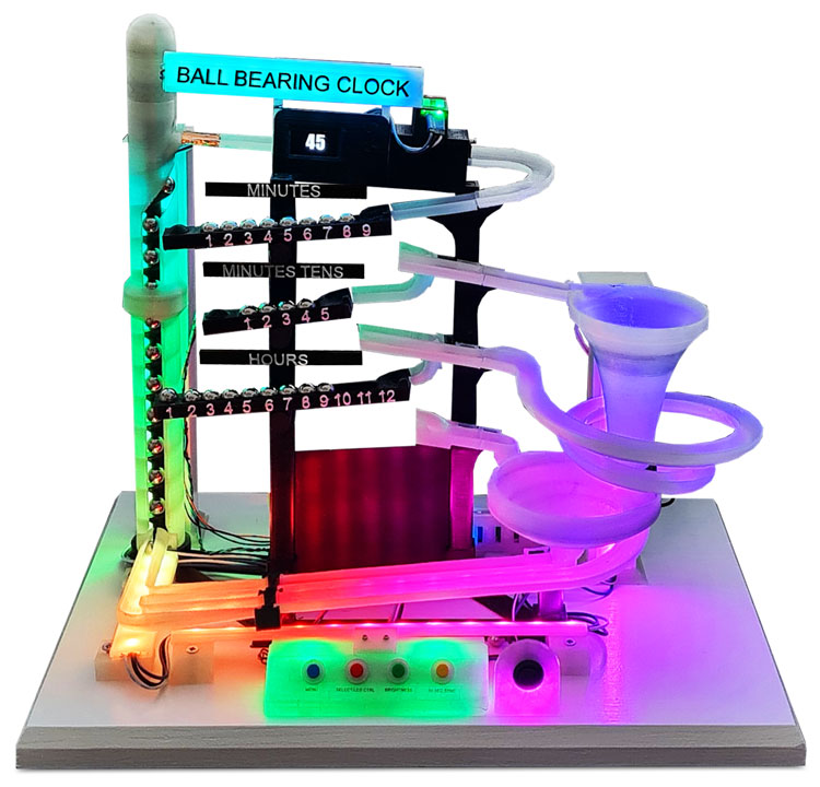
The WS2812B Addressable RGB LEDs can be individually controlled by the Arduino.
I have extended the existing code for the LEDs and changed the wiring to suit.
There are 8 different LEDs modes Rainbow and 7 static single colours and also LED off.
.gif)
Video showing clock change from 12:59 to 1:00 o'clock
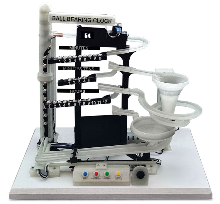
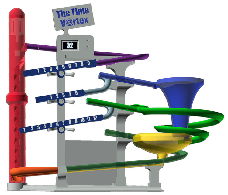
The Original Richard Smith "Time Vortex Clock"
Features
Uses an Arduino NANO
Tells the time using 29 ball bearings
4 clock modes normal time plus 3 demo modes continuous ball feed, 1 second ball feed and 2 second ball feed
Quiet Mode preset and manual. Quiet time can be set in the clock menu. Clock will reset to correct time once Quiet mode is off.
Battery backed up real time clock will restore correct time if power is lost.
1.5" OLED display.
Control buttons built into the display mount.
Illuminated sign built into the clock. LED in sign can be set to 8 colour modes including Rainbow mode.
Optional add-ons on my version
I have used an Atmega 328 built onto Veroboard as this gives a bit more program space compared to the original NANO.
This is the same as an Arduino Uno which can be used instead.
With a few more control options I have designed a control panel seperate from clock.
LED brightness control button on the control panel
Manual 30 second sync button on the control panel
Master clock synchronisation on 30 seconds -ve or +ve pulse.
Seperate power button.
PIR controlled LED lights and OLED display blanking.
50 WS2812B Addressable RGB LEDs for tracks, ball lift , funnels and control panels.
Optical ball detection rather than using the two copper strips
30 Second Synchronization
The original clock keeps very good time with the included RTC but I have added Master Clock Synchronization on 30 seconds if required.
Synchronization can be by a +ve or -ve pulse.
When the clock has not been synchronized the control panel will turn Purple.
On receipt of the 30 second synchronization pulse the control panel will turn Green to show the clock has been synchronized in the last 35 seconds.
The clock can only be synchronized to 30 seconds when the seconds are between 25 and 35.
Outside of this time range the clock panel will go purple to indicate the clock is waiting for the next 30 second sync pulse.
This also stops the clock being repeatedly synchronized by a noisy mechanical sync pulse if a electro-mechanical master is used.
Manual 30 Second Sync is also included.
Main Menu
Pressing the "MENU" button scrolls through the menu
Press the "Select/LED CTRL" button to select a menu item
Seconds Reset
As per Richard Smiths original design seconds are reset to zero using an option in the OLED Menu.
During normal time display press "MENU" repeatedly until "RESET SECONDS" is displayed.
The screen also displays the button to press to reset the seconds "Push select to reset"
On pushing the reset button the seconds are reset and the screen returns to displaying the seconds.
Note I have changed the wording on the menus to "Push select" to match the labeling on my control box.
I have also added a 30 second reset button that will reset seconds to 30 on a single press.
The clock also has the ability to be reset every 30 seconds from a master clock if required.
Demonstration Mode
The clock has 3 Demo modes built in.
Press the "Menu" button until "Change Mode" is displayed.
The current mode will be displayed below.
Pressing the "Select" button will cycle through the 3 demo modes
"Continuous demo"- balls are fed continuously into the clock
"Demo 1 sec delay"- balls are fed into the clock every second
"Demo 2 sec delay"- balls are fed into the clock every 2 seconds
Pressing "Select" again returns to "Normal mode"
Quiet Time Setup
The clock when running is very noisy especially when a 10 min, hour & 1 o'clock "dump" occur.
On my clock with the extra LEDs it is also very bright.
Quiet time sets the clock into silent running and also dims the LEDs.
Quiet time is set in the menu.
Press the menu button until "Quiet Time Setup" is displayed.
Press the "Select" button to setup Quiet time.
On pressing select you will see all the Quiet Time settings.
Start by setting the Current Time.
The setting to be changed is hi-lighted press "Select" to step the setting or "Menu" to step to the next item.
Pressing & holding "Select" will rapidly change the selected setting.
The following can be set after setting the time
Quiet Time Enable/Disable
Start Time of Quiet Time
End Time of Quiet Time
Save
Exit
Quiet time settings are found in myGlobals.h line 9 & 10
const byte
neoPixelNormalBrightness = 10;
const byte neoPixelQuietBrightness = 10;
I have set normal brightness the same as my version of the clock has a separate brightness button
Quiet Time
To set Quiet Time mode press the "MENU" button repeatedly until "Quiet Mode Now" is displayed
Press the "SELECT" button to activate.
The motor stops running and the LEDs dim.
The message "Be quiet.... I'm sleeping. Push button to wake up" is displayed.
Pressing the "Menu" or "SELECT" button returns to normal mode.
The clock will now auto adjust to the correct time by sending the correct number of balls into the clock.
Quiet Time Wakeup
Pressing the "Menu" or "SELECT" button returns the clock to normal mode.
Ball Delivery/Time Stats
This screen shows a few stats about the clock.
EXT is the RTC time and INT is the internal Arduino clock. This shows the drift of the to the Arduino compared to the RTC.
The ball delivery time starts as soon as the motor is activated and stops when the ball detector activates.
Ball Detection
In my clock the ball is detected by an optical sensor.
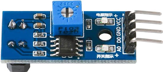
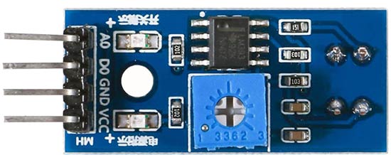
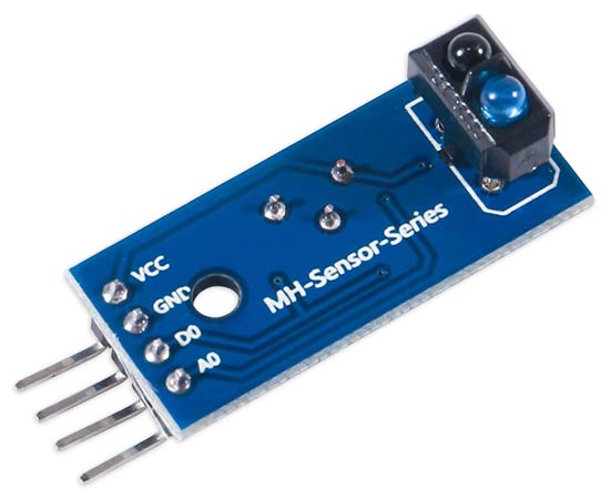
The sensor is a TCRT5000 and I have used a prebuilt module.
The reflectivity of infrared light varies with the color and distance of the reflecting surface.
According to this principle, this IR Reflective Sensor utilizes a TCRT5000 reflective photosensor module to detect color and distance.
When a ball bearing approaches, the signal intensity received by infrared reflective sensor increases and the indicator LED on board turns green and D0 goes high.
When the ball bearing has passed, the intensity decreases (the section of channel below the detector is black) and the LED turns off and D0 goes low.
Sensitivity can be adjusted using the preset resistor on top of the module.
Module Specs
Supply Voltage: 3.3V~5V
Detect distance: 1mm-15mm
Digital Outputs HIGH when
objects detected
TCRT5000 Modules
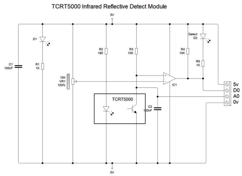
TCRT5000 Module Schematic
Conect D0 (digital) to Arduino D2 pin.
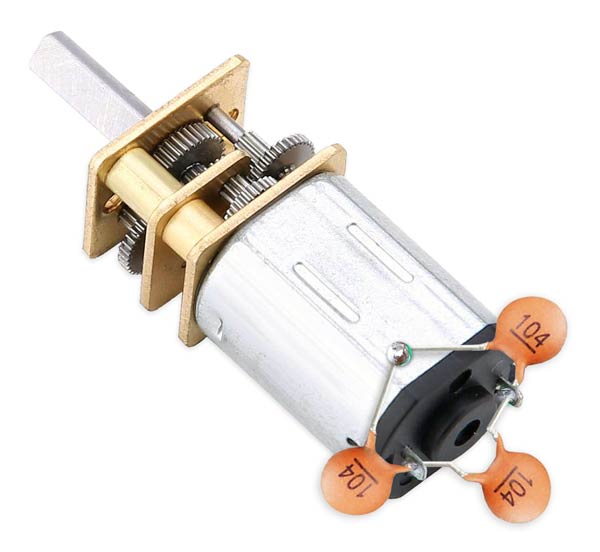
Motor
My motor is a N20 metal gear motor 100RPM 12v.
A 100RPM 6v motor is used on the original clock but there is built in code to adjust the motor speed.
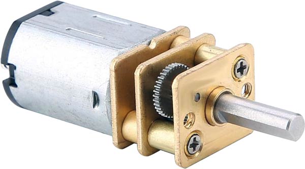
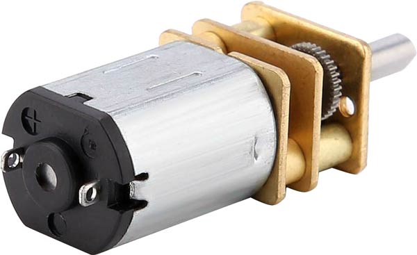
The motor when running makes a lot of electrical noise so 3 capacitors are connected to the motor coils as shown below.
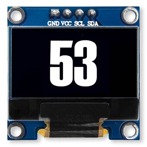
OLED
This clock uses a .96 inch 128x64 I2C SSD1306 OLED display.
The display uses the same 2 wire bus as the RTC.
About OLEDs
OLED (Organic Light Emitting Diodes) is a flat light emitting technology, made by placing a series of organic thin films between two conductors.
When electrical current is applied, a bright light is emitted.
OLEDs are emissive displays that do not require a backlight and so are thinner and more efficient than LCD displays (which do require a white backlight).
RTC
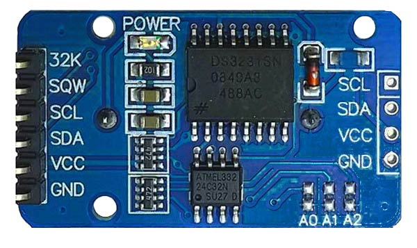
I have modified my RTC to use non rechargeble batteries.
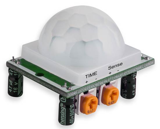
PIR
As my version of the clock has a lot more LEDs I have added a PIR function to turn the LEDs and OLED display off when noone is in the room.
When a positive voltage is applied to the PIR pin the LEDs and OLED display light up.
A PIR module below will work directly with the clock.
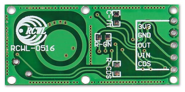
Microwave Motion Sensor
If the clock is in a perspex or glass case then the PIR sensor above will not work unless it is wired outside the case.
A Microwave Motion Sensor can be used instead.
Microwave Motion Sensor module RCWL-0516.
There is no timer built into this module but some simple code to trigger after a set number of minutes if the output is Low can be added.
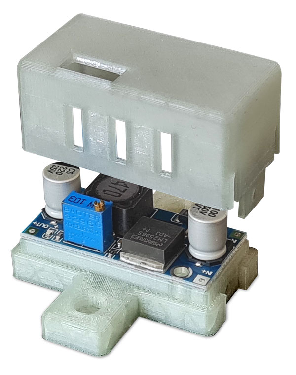
Power Module
LM2596 DC to DC High Efficiency Voltage Regulator 3.0-40V to 1.5-35V
This module can supply upto 3A if fitted with a heat sink.
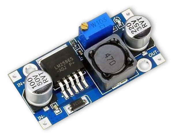
The module is housed in a 3D printed case screwed to the base board.
The case can be downloaded from Thingiverse.
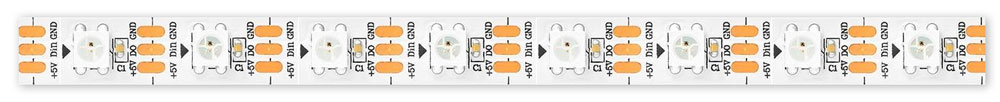
LED Schematic
I have used a 60 LED WS2812B RGB 5050 SMD Strip.
50 LEDs are used in total.
The strips cut be cut into any size strip by cutting at the guide marks.
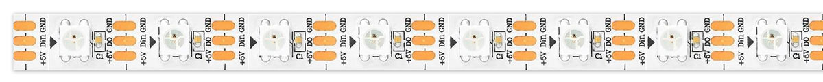
Strips are split and wired as per the diagram below.
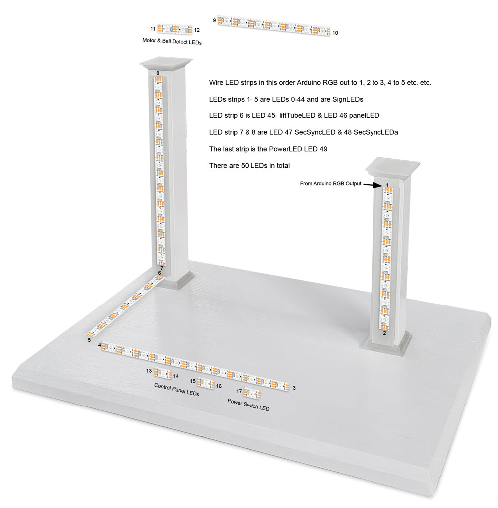
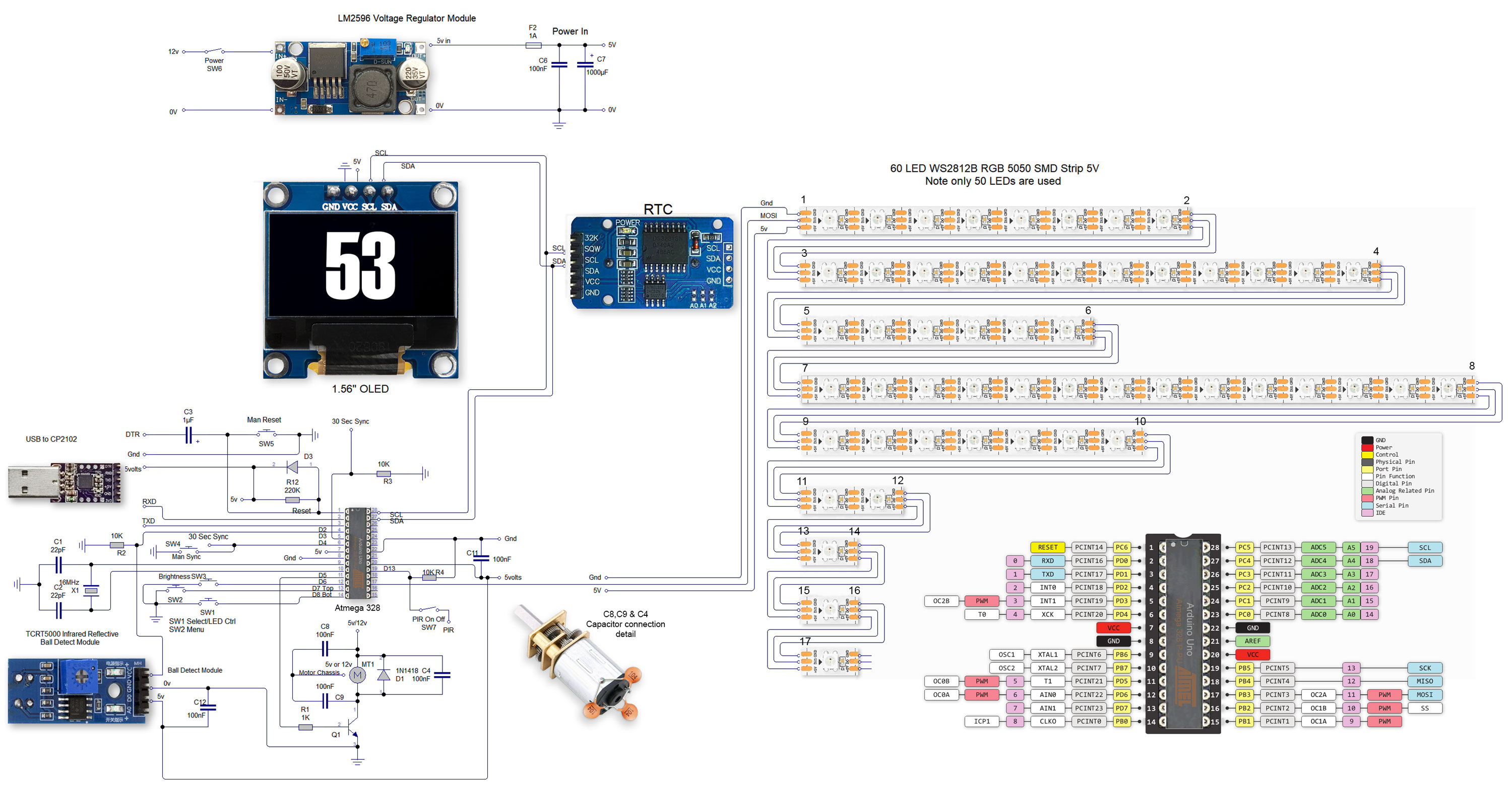
Schematic
Click to show full size version
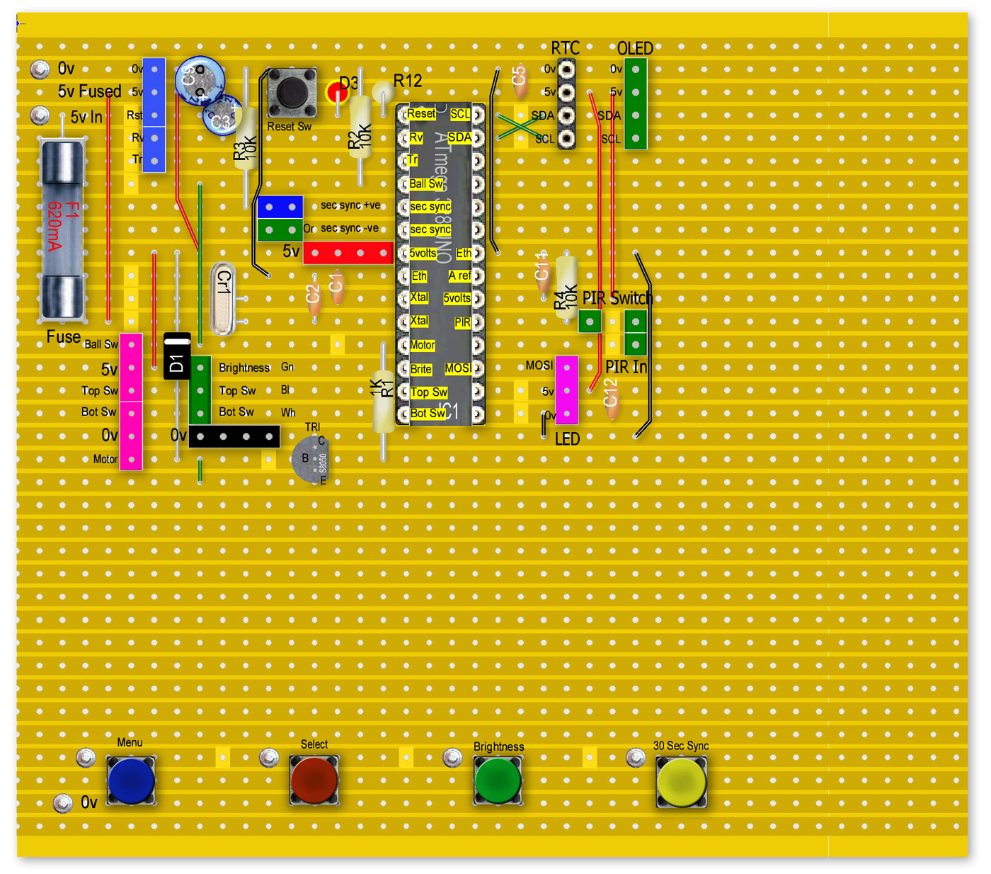
Veroboard Layouts
Veroboard layout main board top and control panel lower
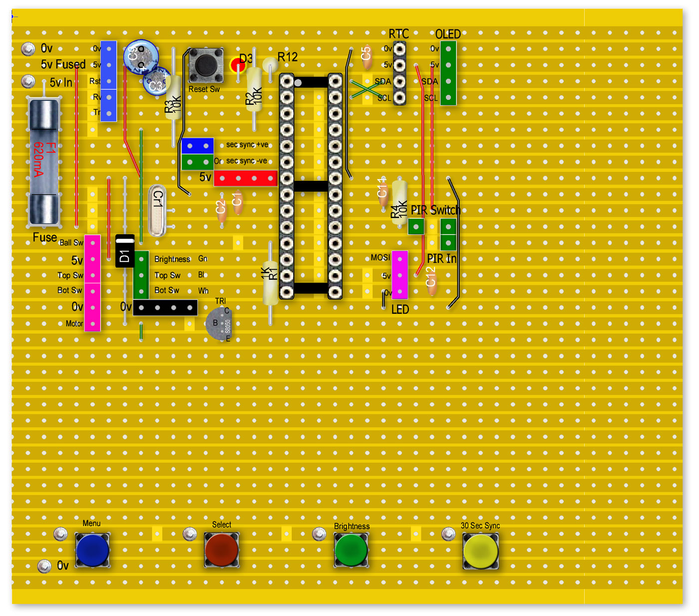
Veroboard layout showing Atmega 328 (Arduino Uno) and pin layout
Veroboard layout rear. Note the wire link on the rear of the board.
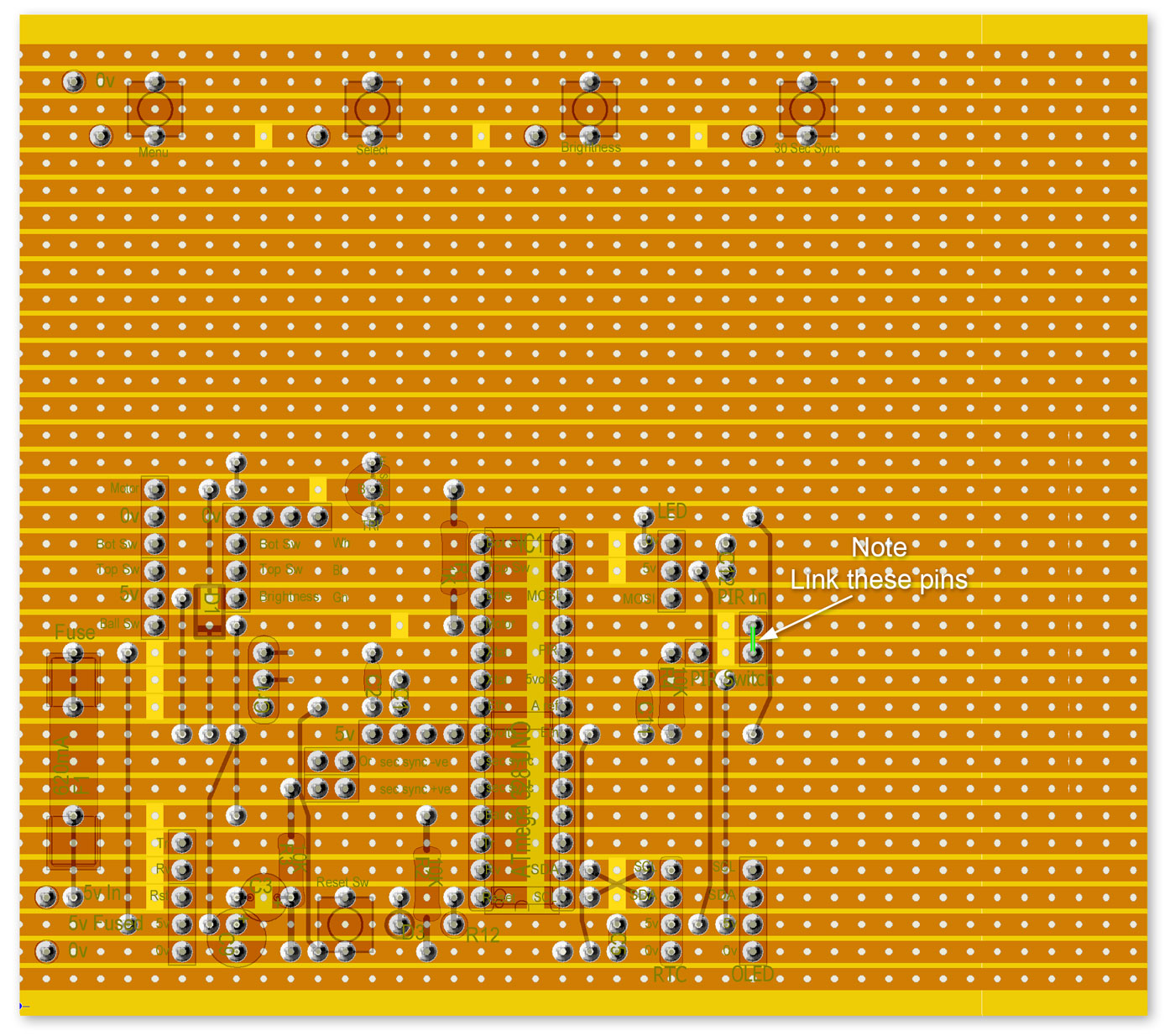
There is a 3D printed spacer for the Verobaord. The spacer also covers the area under the Atmega 328 to support the Veroboard during chip insertion.
The board is cut the exact size of this spacer to allow the cover to fit.
![]()
![]()
Construction
Full details of the original clock and all parts can be found here on Thingiverse
Also included is the original Arduino NANO code and instructions.
3D Printing detail from the original version
| Part Num | Part | Quantity | Support | Infill | Other Notes |
| 1 | support_Base.stl | 1 | None | ||
| 2 | support_Arm.stl | 1 | None | 30% Infill | |
| 3 | support_MainTrack.stl | 1 | Everywhere | 30% Infill | |
| 4 | support_WideFunnel.stl | 1 | Build Plate | 30% Infill | |
| 5 | support_LiftTubeEntryTrack.stl | 1 | Build Plate | 30% Infill | |
| 6 | support_TopBraceWithDisplayHolder.stl | 1 | Everywhere | Trim top of opening to the bezel | |
| 7 | ds_DisplayCover.stl | 1 | Build Plate | Need to be careful to not break the spiral when removing from build plate | |
| 8 | ds_SignCover.stl | 1 | Everywhere | ||
| 9 | ds_Button.stl | 2 | None | ||
| 10 | ds_ButtonClip.stl | 2 | None | ||
| 11 | ds_DisplayClip.stl | 1 | None | ||
| 12 | circuitBoardHolder.stl | 1 | None | ||
| 13 | circuitBoardCover.stl | 1 | None | ||
| 14 | ds_SignColorInsert.stl | 1 | None | Use translucent material | |
| 15 | ds_SignInnerBox.stl | 1 | None | Use translucent material | |
| 16 | arm_Hours-WithInlayHoles.stl | 1 | Build Plate | Or use alternate arms with raised numbers | |
| 17 | arm_Minutes-WithInlayHoles.stl | 1 | Build Plate | Or use alternate arms with raised numbers | |
| 18 | arm_TensMinutes-WithInlayHoles.stl | 1 | Build Plate | Or use alternate arms with raised numbers | |
| 19 | arm-BallCap(.x-Tol).stl | 2 | None | Pick the one with desired tolerance | |
| 20 | arm-Pin(.x_Tol).stl | 3 | None | Pick the one with desired tolerance | |
| 21 | arm-Inlay-Set.stl | 3 | None | 0.4 Wall Thickness | Not needed if using alternate arms, can be tricky to print |
| 22 | liftTube_Bottom.stl | 1 | Build Plate | ||
| 23 | liftTube_Top.stl | 1 | None | ||
| 24 | liftTubeAuger_Bottom.stl | 1 | None | ||
| 25 | liftTubeAuger_Top.stl | 1 | None | ||
| 26 | liftTubeAugerConnector.stl | 1 | None | ||
| 27 | liftTubeCap(WithSupport).stl | 1 | None | 30% Infill | Has support built into the part, use visualization_LiftTubeCap.stl if you want all support to be done with your slicer |
| 28 | liftTubeCap_Dome.stl | 1 | None | ||
| 29 | liftTubeCap_LEDPlate.stl | 1 | Build Plate | ||
| 30 | track_HoursReturn.stl | 1 | None | ||
| 31 | track_HoursExit.stl | 1 | Build Plate | ||
| 32 | track_TensMinutes.stl | 1 | None | ||
| 33 | mf_TensMinsSpiral(WithSupport).stl | 1 | Build Plate | Has support built into the part for the spiral but still needs support generated for the top connector, use visualization_TensMinsSpiral.stl if you want all support to be done with your slicer | |
| 34 | track_Minutes2TensMins.stl | 1 | None | ||
| 35 | track_TensMins2Hours.stl | 1 | None | ||
| 36 | track_Minutes.stl | 1 | None | ||
| 37 | mf_TallFunnel.stl | 1 | Build Plate | ||
| 38 | mf_TallFunnelTrack.stl | 1 | Build Plate | ||
| 39 | mf_TallFunnelBottomMount.stl | 1 | None | ||
| 40 | mf_WideFunnel.stl | 1 | Build Plate | ||
| 41 | track_WideFunnelExit.stl | 1 | Build Plate | ||
| 42 | track_LiftTubeExit(WithBrim).stl | 1 | Build Plate | Has brim around the upper connector to encourage cura to add support there. | |
| 43 | track_Feeder2Minutes.stl | 1 | None | ||
| 44 | track_LiftTubeEntry.stl | 1 | Build Plate | ||
| 45 | squareCap(.x_Tol).stl | 14 | None | Pick the one with desired tolerance | |
| 46 | cableClip-HH.stl | 1 | Build Plate | Used on circuit board holder | |
| 47 | cableClip-HTop.stl | 1 | None | Used on topBraceWithDisplayHolder | |
| 48 | cableClip-HV.stl | 1 | Build Plate | Used on bottom of lift tube | |
| 49 | cableClip-V-Offset.stl | 1 | None | Used on circuit board holder | |
| 50 | cableClip-V-Small.stl | 1 | None | Used on lift tube cap | |
| 51 | cableClip-V.stl | 6 | None | 4 used on lift tube, 1 on circuit board holder, 1 on topBraceWithDisplayHolder | |
| 52 | optional_adjustableBaseFoot.stl | 5 | None | Can be used to level the clock if needed | |
| 53 | alt_arm_Hours-RaisedNumbers.stl | 1 | Build Plate | Can be used instead of the arm with inlay | |
| 54 | alt_arm_Minutes-RaisedNumbers.stl | 1 | Build Plate | Can be used instead of the arm with inlay | |
| 55 | alt_arm_TensMinutes-RaisedNumbers.stl | 1 | Build Plate | Can be used instead of the arm with inlay | |
| 56 | alt_support_Base.stl | 1 | None | Base with a solid bottom. Might be a better choice if using a non-slip liner to keep the clock from vibrating around | |
| 57 | visualization_InlaySetArmHours.stl | Just used to load all the parts of the clock in openscad for visualization | |||
| 58 | visualization_InlaySetArmMinutes.stl | Just used to load all the parts of the clock in openscad for visualization | |||
| 59 | visualization_InlaySetArmTensMinutes.stl | Just used to load all the parts of the clock in openscad for visualization | |||
| 60 | visualization_LiftTubeCap.stl | Just used to load all the parts of the clock in openscad for visualization | |||
| 61 | visualization_TensMinsSpiral.stl | Just used to load all the parts of the clock in openscad for visualization | |||
| 62 | visualization_track_LiftTubeExit.stl | Just used to load all the parts of the clock in openscad for visualization |
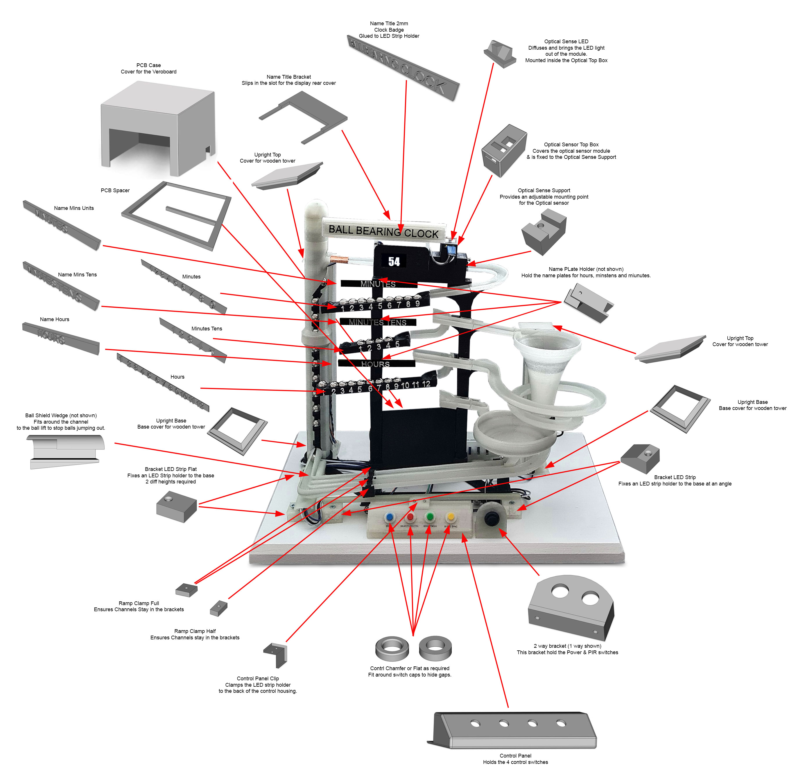
My 3D Printed Parts
Most of the 3D parts used in this clock were designed by Richard Smith and are available on his Thingiverse page here
These files were designed by myself and while some are essential for my build others are optional.
The picture below shows where my parts are located.
Click to see full size picture.
All files are available on Thingiverse but I have included a zip with my stl and Freecad files below.
Individual List of my 3D Parts
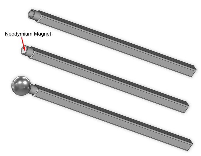
Ball Bearing Pickup Tool
One thing I noticed when building/adjusting this clock was often ball bearings would jump out or I would just drop them.
I designed a simple ball bearing pickup tool to pick up ball bearings from awkard places.
It's simply a stick with a hollow end to take a 5mm neodymium magnet.
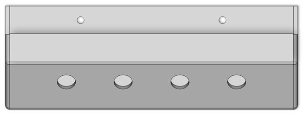
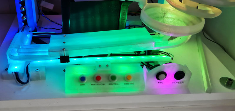
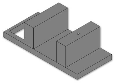
Control Panel
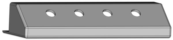
Top view showing fixing holes to wooden base
Control Panel LED Strip Fixing Clip
This part hold a Thin LED Strip Mount to the Control panel.
2mm self tappers fix it to the LED Strip Mount and control panel top
Fixing clip attached to top of control panel with LED strip at rear
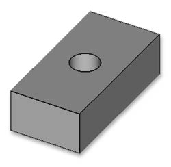
Control Panel Spacer
This spacer holds the control panel switchesswitches a set distance from the control panel rear face.
![]()
Control Switch Button Covers
These covers just fit around the switches on the control panel
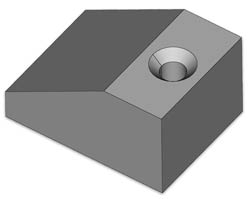
Channel Ball Keeper Wedge
I found every now and then balls would jump out of the ball lift feed channel where the minutes & hours channels meet.
This just fits over the ball lift feed channel & is glued to the LED strip below.
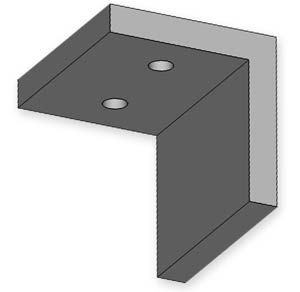
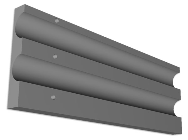
LED Strip Bracket Mount Angled
A pair of these fixed to the back board angle an LED strip up through the Hour & Minute ball channels.
LED Strip Bracket Mount Flat
A pair of these fixed to the back board angle an LED strip vertically up through the Ball lift ball channel.
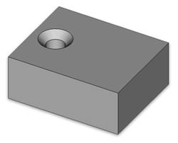
Ramp Clamp Full
Secures the Hours/Mins channels to their brackets if they tend to work loose
Not required if ramp cover is fitted.
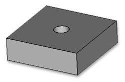
Ramp Clamp Half
Secures the Hours channel to their brackets if they tend to work loose
Not required if ramp cover is fitted.
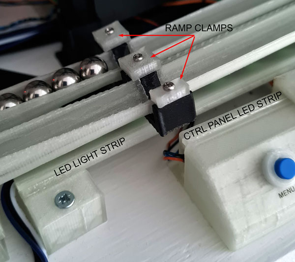
Locations of ramp clamps with m2 self tappers
Cover Hour & Minutes Ramps
I found that every now and then a ball would be ejected from the clock after a hour dump.
It seems as the balls shot down the hour and minute ramps they would back up to the ramps and at a high speed ball bearing comming down the ramp
would sometimes be ejected when it hit a staionary ball bearing. This would happen once or twice a day.
I have now fitted a cover for the hour and minute ramps that fixes to the ramp holder with 3 self tappers.
If this cover is in place then the 3 ramp clamps above are not required.
Cover in place over the hour & minute ramps
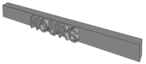
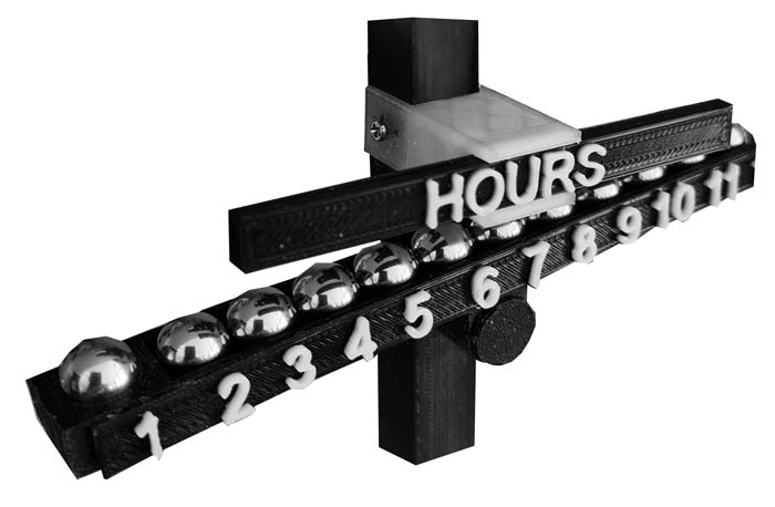
Hours Name Plate
Fixed in place with a name plate holder this is the Lable for the hours.
Designed to be printed in 2 colours (see instructions on my 3D printer page) .
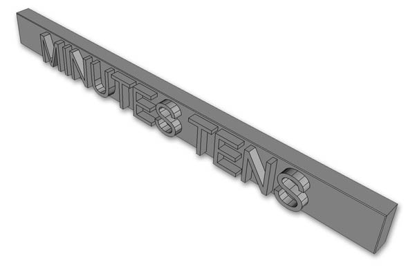
Minutes 10s Name Plate
Fixed in place with a name plate holder this is the Lable for the minutes 10s.
Designed to be printed in 2 colours (see instructions on my 3D printer page) .
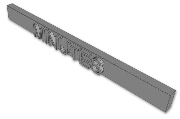
Minutes Name Plate
Fixed in place with a name plate holder this is the Lable for the minutes .
Designed to be printed in 2 colours (see instructions on my 3D printer page) .
Name Plate Holder
A single 2mm self tapper holds the bracket the left hand the support arm main section while the name plates are held in place with glue.
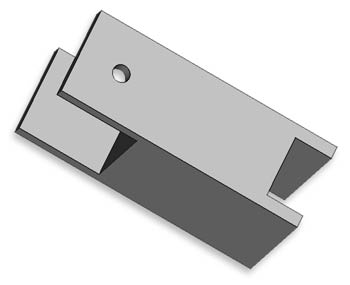
This image shows the hour name holder in place on the support arm with the 2mm self tapper in place.
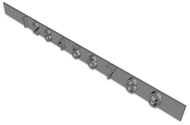
Hours Numerals
Designed to be printed in 2 colours (see instructions on my 3D printer page) the the thin background strip is glued to the ball hours display holder.
Minutes Tens Numerals
Designed to be printed in 2 colours (see instructions on my 3D printer page) the the thin background strip is glued to the mins tens display holder.
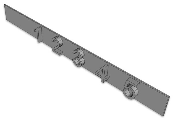
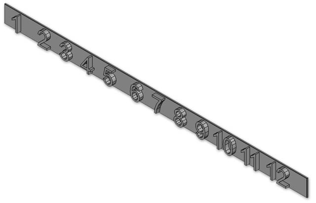
Minutes Numerals
Designed to be printed in 2 colours (see instructions on my 3D printer page) the the thin background strip is glued to the minutes display holder.
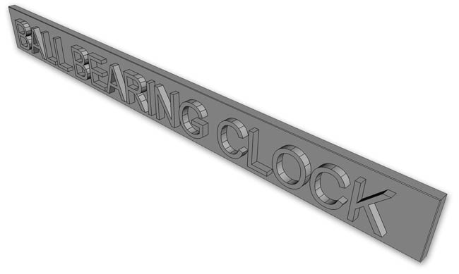
Clock Name
The clock name is designed to be printed in 2 colours (see instructions on my 3D printer page) and is glued to the clock name bracket LED cover.
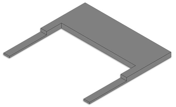
Clock Name Bracket
On my clock the rear of the OLED housing is not fitted.
This bracket just slips down the channels for the rear housing.
A thin LED cover strip is screwed to this bracket and the clock name is glued to the front of the LED strip cover.
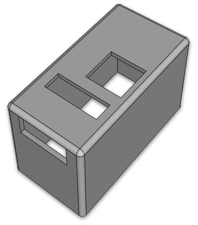
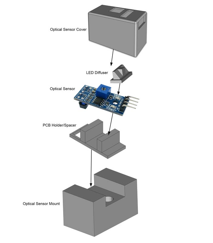
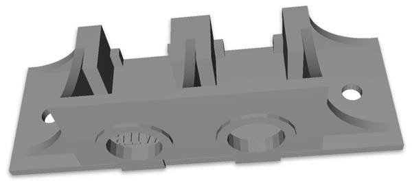
Optical Ball Detector
Optical ball detector cover
Ball detection is carried out by a The TCRT5000 Infrared Reflective Ball Detect Module.
These sensors are sensitive to UV light especially sunlight so need to be mounted in a box.
The box can be covered in metal foil if required.
The box has cutouts for wiring connections at the front, sensitivity adjustment at the top as well a LED indicators power & ball detect.
Ball detect PCB mount
This part spaces the PCB from the top of the cover with a 2mm self tapper fixing it through the PCB mount hole.
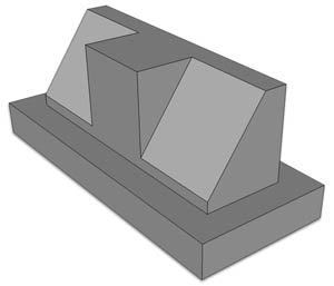
LED Diffuser
The ball detect module PCB has LEDs for power and ball detect these shine up through the LED diffuser and out the top of the housing.
Fitted up from the inside of the ball detect cover the angled faces face forward. The square face between the angles can be blacked ot with paint or an indellible marker if required.
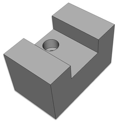
Optical Ball Detector Mount
The mount holds the detector the correct distance away from the ball channel.
Horizontal adjustment is carried out by sliding the detector housing in the mount.
A self tapper in the mount holds it in place when adjusted.
The mount itself is fixed by a recessed self tapper to the OLED bracket.
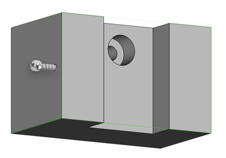
View showing the modified Optical ball sensor cover adjustment lock screw location.
A 1.5mm hole is drilled through the side and a 2mm self tapper screw through until it touches the Optical sensor cover to lock it in place.
Download the modified parts here as they are not in the main zip file Cura FreeCad
Optical Ball Detector Assembly Diagram
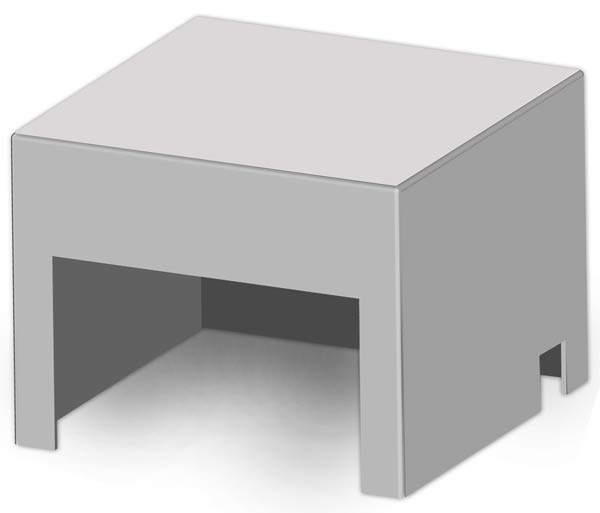
Veroboard/Arduino Uno Cover
I decided not to use the mounting on the clock ifself but mount the Veroboard on the wooden base board.
The cover is designed to fit my Verobaord layout but Freecad files are included so you can change the size to suite.
If you are using an Arduino Uno then you can adjust it to fit that as well.
My cover friction fits over my PCB Spacer so this can be adjusted to suit your boards as well.
Verobord Spacer
Fits under the Veroboard to keep the soldered pins off the baseboard.
Also acts as a cutting template for the Veroboard.
Not required if the board is fitted inside the clock as per the original design.
![]()
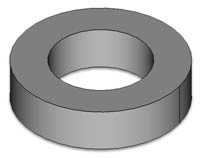
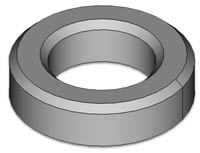
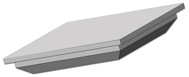
LED Stip Tower Decorative Finials
The LED strips for the ball lift and funnels are mounted verticaly on wooden posts.
These parts just finish off the plain wooden posts.
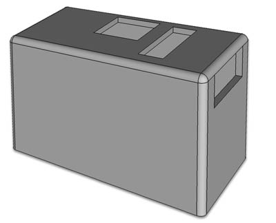
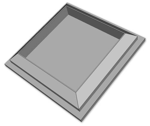
Top cover
Top cover inside detail
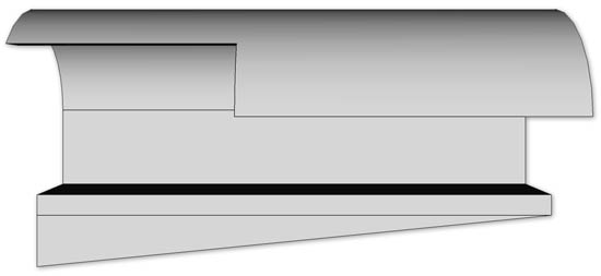
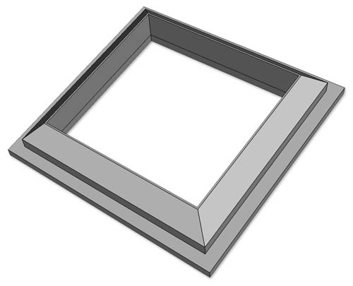
Base cover detail
The clock is built onto a base board with a couple of wooden towers to support the lift tube & funnel LEDs.
3D printed decortive caps are clipped on the wooden supports.
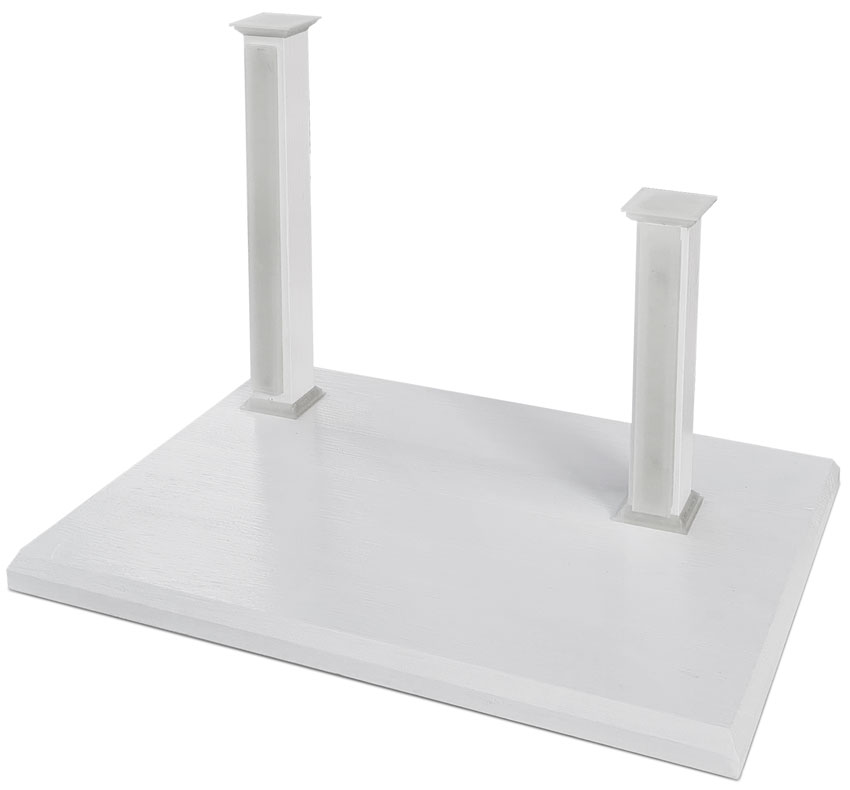
The LED strip is a WS2812B RGB 5050 SMD 5V Addressable.
The LED strip is housed a 3D printed LED strip holder that can be downloaded from Thingiverse
Imported 3D Parts
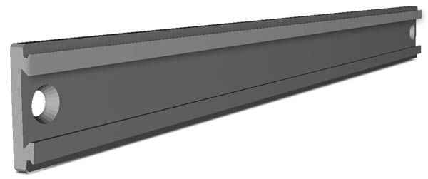
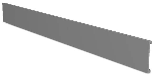
Thin LED Strip Mounts
To mount the LED strips I found these Thin LED Strip Holders on Thingiverse.
The LED strip is very thin and the LEDs strip are held in place once the cover is on.
The design includes multiple lengths and connectors.
I just used the straight lengths on this clock and cut them down where required.
I had to drill and countersnk my own holes where required.
LED strip base.
LED strip cover
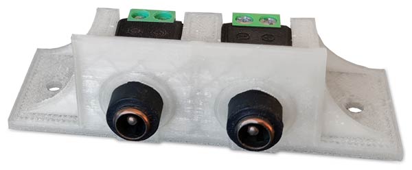
Plug & Jack Holder
These are available from Thingiverse and are available in many options.
I have used the double version.
One jack does the 12v input and the other 30 second sync and PIR input.
CODE
Before compiling and to save about 1.5k of flash memory comment out the if/else section with the drawBitmap calls in the constructor in Adafruit_SSD1306.cpp
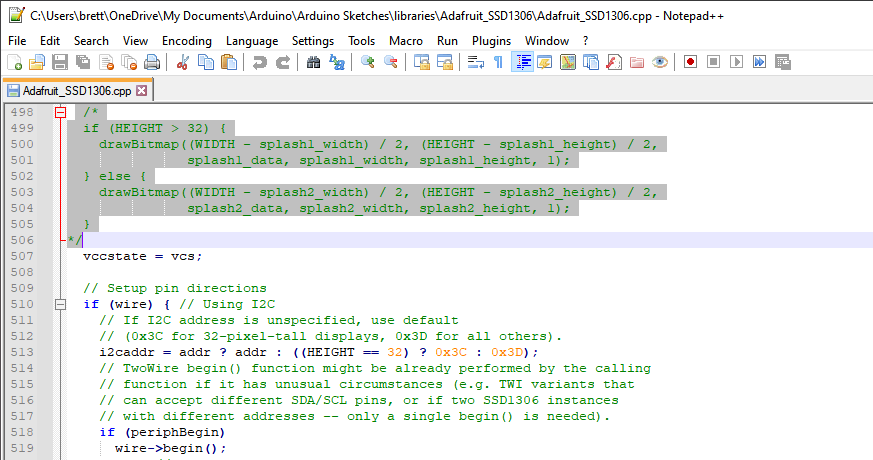
Download Arduino Code