Home Master Clock LCD Master Clock Kenley Weather
Section Top Feeding Design Construction Electronic Modules Veroboards Stepper Motor Schematic Code
 |
|
This project uses an ESP8266 WIFI board or Arduino NANO to trigger a measure of dry food for your Pet or in a suitable outdoor enclosure Koi Carp pellets. To make the project simple a Smart WIFI plug powers the feeder and a pan and tilt camera monitors the feeding. The feeder uses the hopper from a cereal feeder and has a stepper motor attached to the feed flaps to rotate them an exact dose of dry food. The hopper can give out 34 measure of food so depending on the feeding levels and or number of pets being fed it should be suitable for a number of days feeding. |
If you want a more complex pet feeder then I have made a BLYNK version some time back which will need some re-working to work on the new BLYNK
Feeding
Feeding starts on power up then stops after a preset number of feed measures.
The feeder is then powered off.
The feeding is controlled by a Tapo TP100 smart plug and can be set to feed on a schedule or manually.
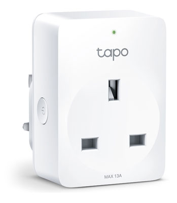
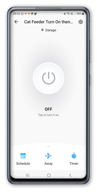
To feed just open the TAPO app and select the name of your feeder in this case CAT Feeder.
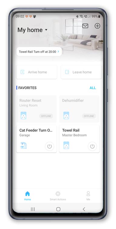
Manual Feeding
Turn on the feeder by tapping the button.
While the feeder is on the LED strip behind the feed tray is on.
Check on the camera that there is feed in the feed tray then turn off.
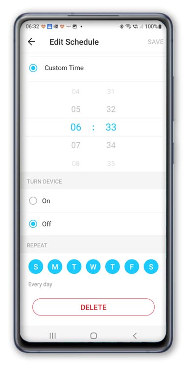
Scheduled Feeding
To set a schedule just set an ON time and then an OFF time 1 minute later.

WIFI CAM Monitor
I use a wireless Pan and tilt camera to make sure the feeder is working correctly.
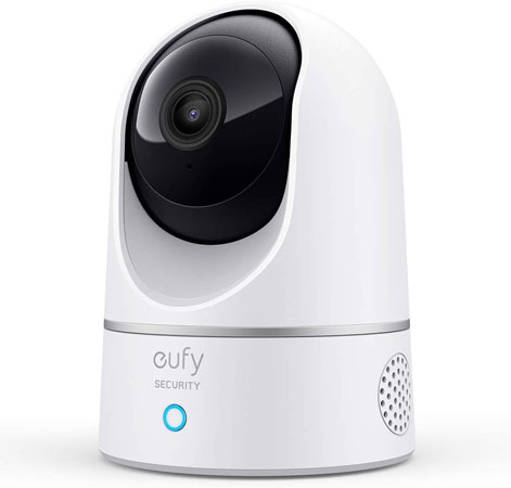
Using the Eufy app to monitor the feeder.
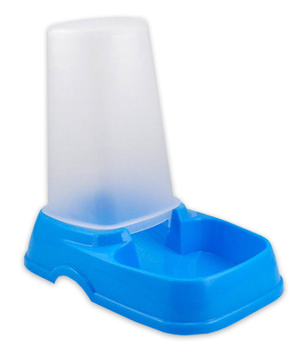
Water
Make sure your cat has enough water while you are away by using one of these water dispensers.
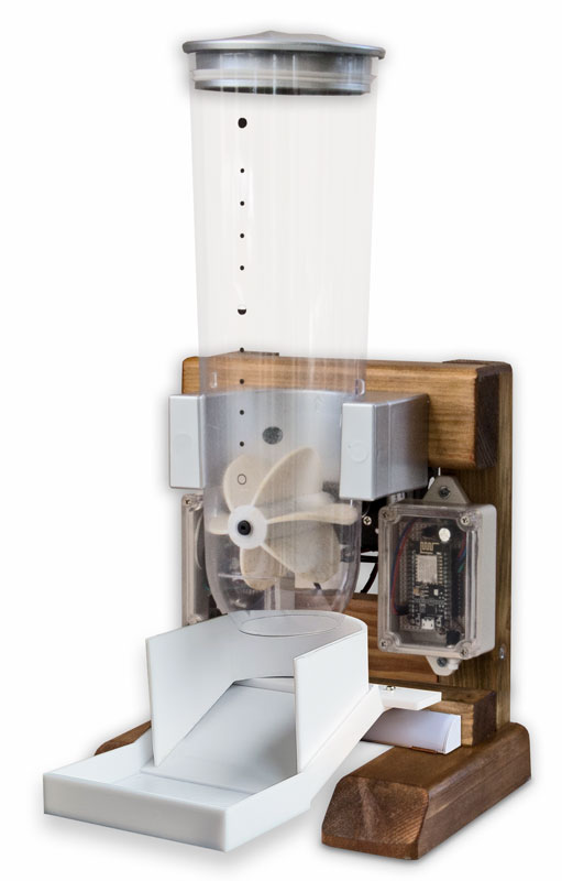
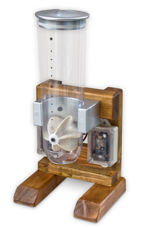
Design
The feeder is built onto a wooden frame and can be custom sized to suit.
I used the taller frame in a kitchen base unit in my utility room but then cut it down to make a shorter more stable frame to use freestanding on the floor.
If fitting into a kitchen base unit a 300mm minimum cabinet width should be fine.
Using a short length of standard 68mm down pipe cut through the base of the cabinet and a 112.5
Offset Bend to allow the pipe to exit the cabinet through the plinth and into the cat/dog bowl.
Once the feeder operates gravity will take the feed down the pipe and into the bowl.
The free standing model has a 3D printed feed bowl and an optional LED strip fitted to illuminate the feeder when operating.
Construction
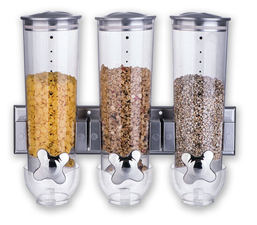
The feeder uses parts from a commercial cereal dispenser.
The dispensers are available as single, double or triples on Ebay.
The cost between the different types is quite low so I went for the triple so I had some spare parts.
If you go for the type shown below they are very easy to modify.
Disassembly of the Cereal Dispenser
To take apart of old dispenser remove the dispensers from the wall mounting brackets.
Then remove the brackets from the wall mont. The brackets are fixed to the plastic wall mounts by two self tapping screws, remove them all.
The brackets can then be re-used in the final project.
Note when fixing the brackets to the new feeder use flat head screws and don't
over tighten or the plastic on the brackets could break away.
Once removed it the bracket carefully fixed to the new wooden mounting frame with flat headed wood screws.
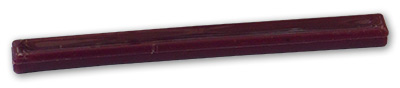
The old hand lever is pulled out of the dispenser with the plastic D shaft.
The plastic D shaft is then pulled out of the hand lever ready to be fixed to the motor coupler.
The plastic handle is not used in this project.
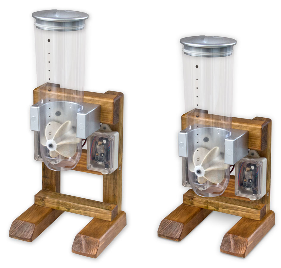
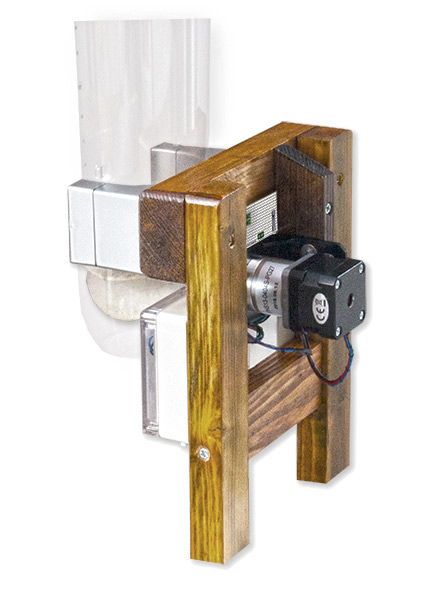
Below single feeder mounted on it's original plastic bracket in a wooden feeder stand.
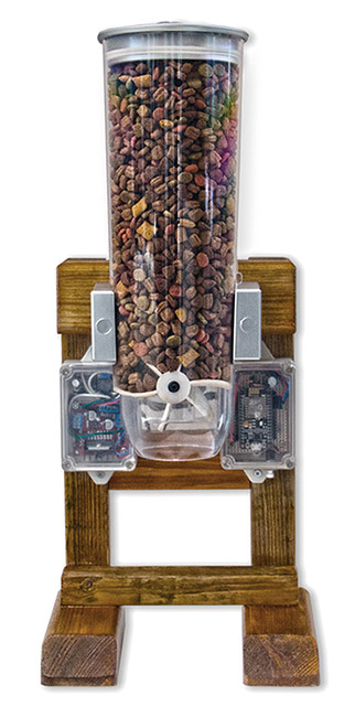
The feeder sits on a stand made from off cuts of wood.
These sizes are not that important and can be changed to suit the timber/ cupboard space as required.
All joints are simple screw joints and timer is stained then varnished.
The power supply and L298N H bridge modules are housed on the left.
The ESP8266 module on the right.
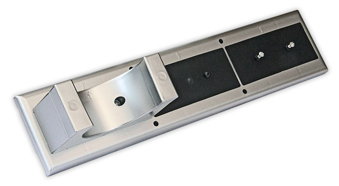
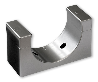
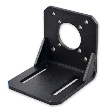
The stepper motor mounting bracket is fixed to a wooden block.
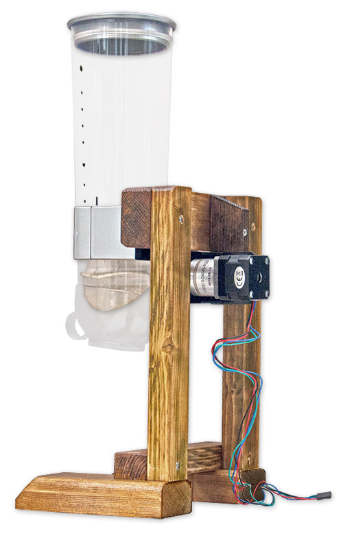
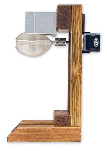
The stepper motor shaft is connected to the feeder drive shaft by a motor shaft coupler.
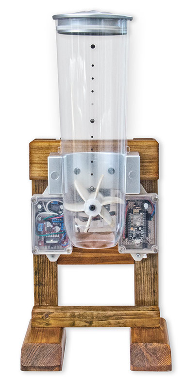
Once the feeder is constructed the rubber feed flaps will need adjusting so they give a full feed on the set rotation of the stepper motor.
This is carried out by pressing the calibrate button repeatedly until the feed flaps are in the correct position.
Below setting up the feeder
Above the feeder flaps are not in the correct position to give a full measure of feed.
Pressing the calibrate button moves the flaps a fraction of a turn to ensure a full measure of feed each time.
Below adjusted flaps producing a full measure of feed.
Electronics
I have used modules where possible to keep the design and construction of this project as straight forward as possible.
Veroboard is used to mount some of the components/modules there is no PCB layout or design.
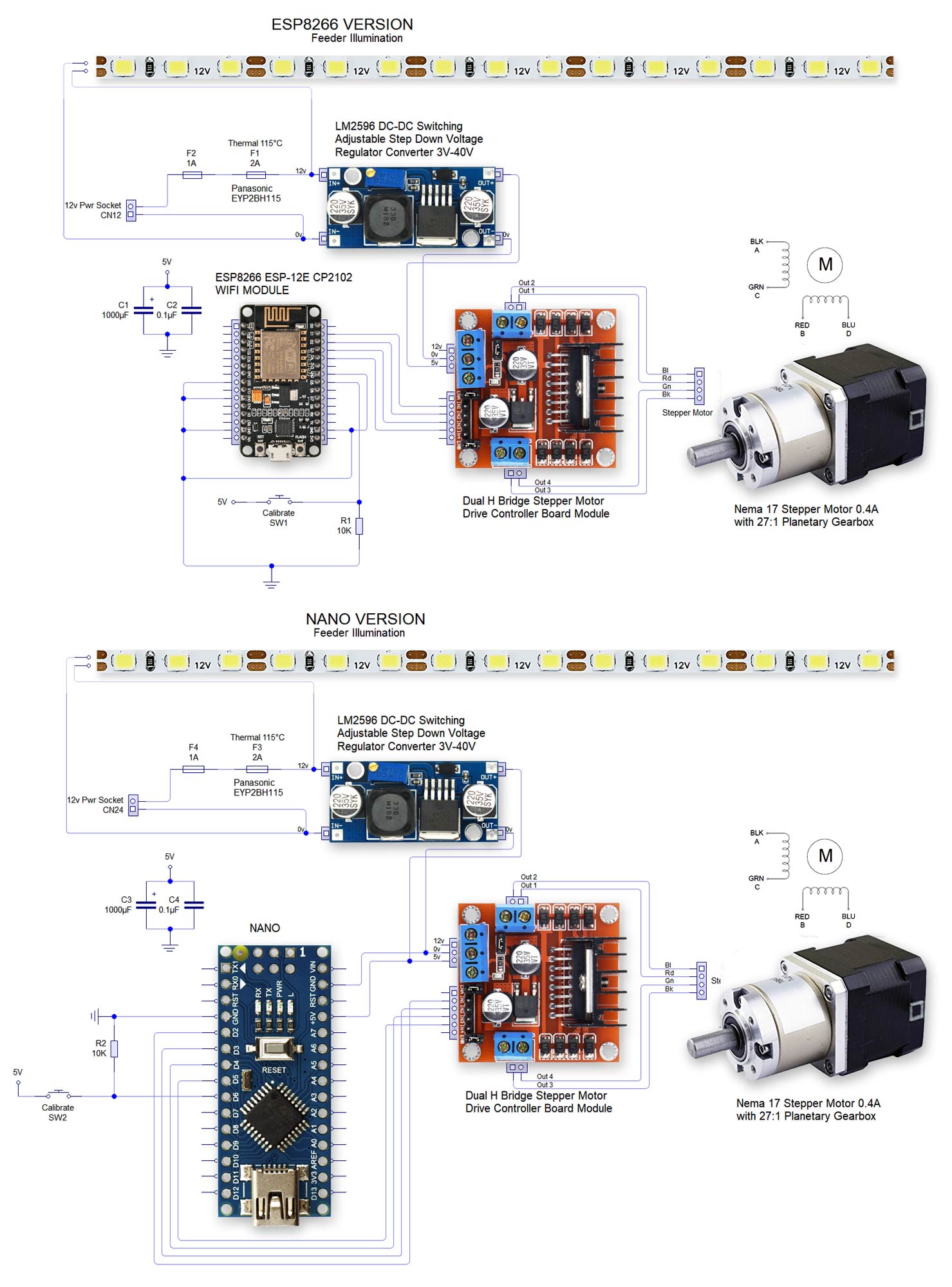
I have used a fuse on the main 12v input to this project. The power cable is rated at 2 amp and I have used a 1 amp fuse. I have also fitted a thermal fuse attached
to the stepper motor housing as as additional safety device. The measured current draw with motor running and mobile phones running as IP servers is 250mA.
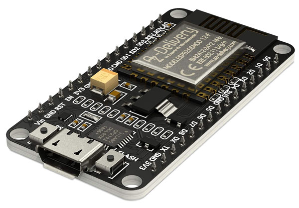
NANO/ESP8266 module
I modified my original IOT Pet Feeder using the Blynk Mobile App so just used the ESP8266 module from that project.
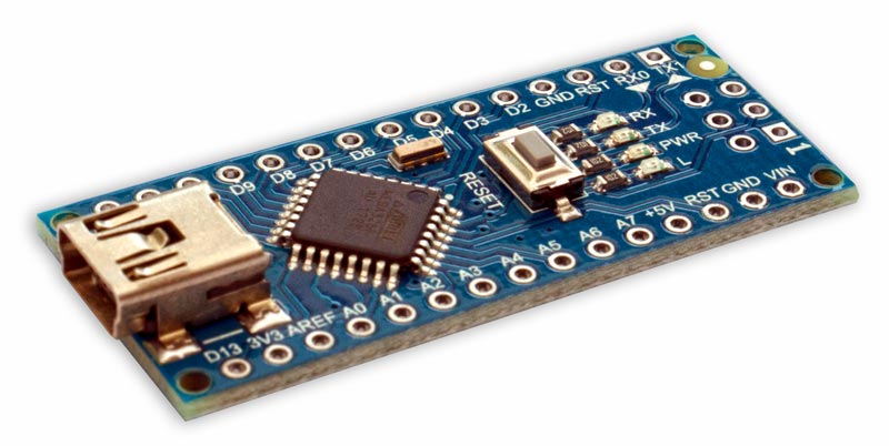
If I was to build from scratch I would use an Arduino NANO.
ESP8266
Arduino NANO
Voltage Regulator Module LM2596
Power for the L298N, ESP8266 module and the Samsung S3 mobile phone is delivered by a LM2596 DC to DC converter.
The 12v feed used by the stepper motor is dropped down to 5volts.
The circuit uses 160mA with the mobile On (display off) and the video server app running.
This rises to 250mA wit the the stepper motor running.
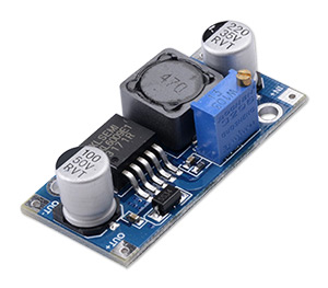
Voltage Regulator Module LM2596
Specifications:
Rectification mode:Non-synchronous rectifier
Module property:Non-isolation buck
Input voltage:4V-40V
Output voltage:1.5V-34V(Adjustable)
Output current:Rated current is 2A,maximum 3A(Additional heatsink is required)
Conversion efficiency:92%( highest )
Switching frequency:65KHz
Output ripple:30mV( maximum )
Voltage regulation: 2.5%
Load regulation: 0.5%
Dimension:43mmx21mmx14mm(LxWxH)
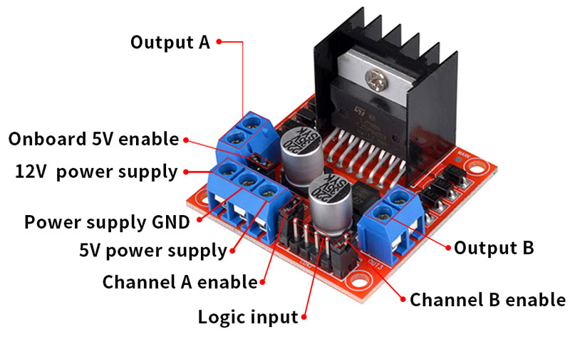
Motor Drive Controller Board Module L298N Dual H Bridge DC Stepper
|
Specifications L298N as main chip
|
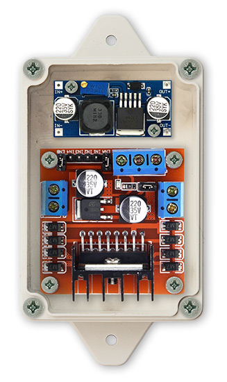
Module and Board Layouts
The modules are housed in Perspex topped boxes
The LN298 H Bridge stepper motor module and DC to DC converter in 1 box.
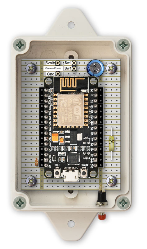
ESP8266 Version
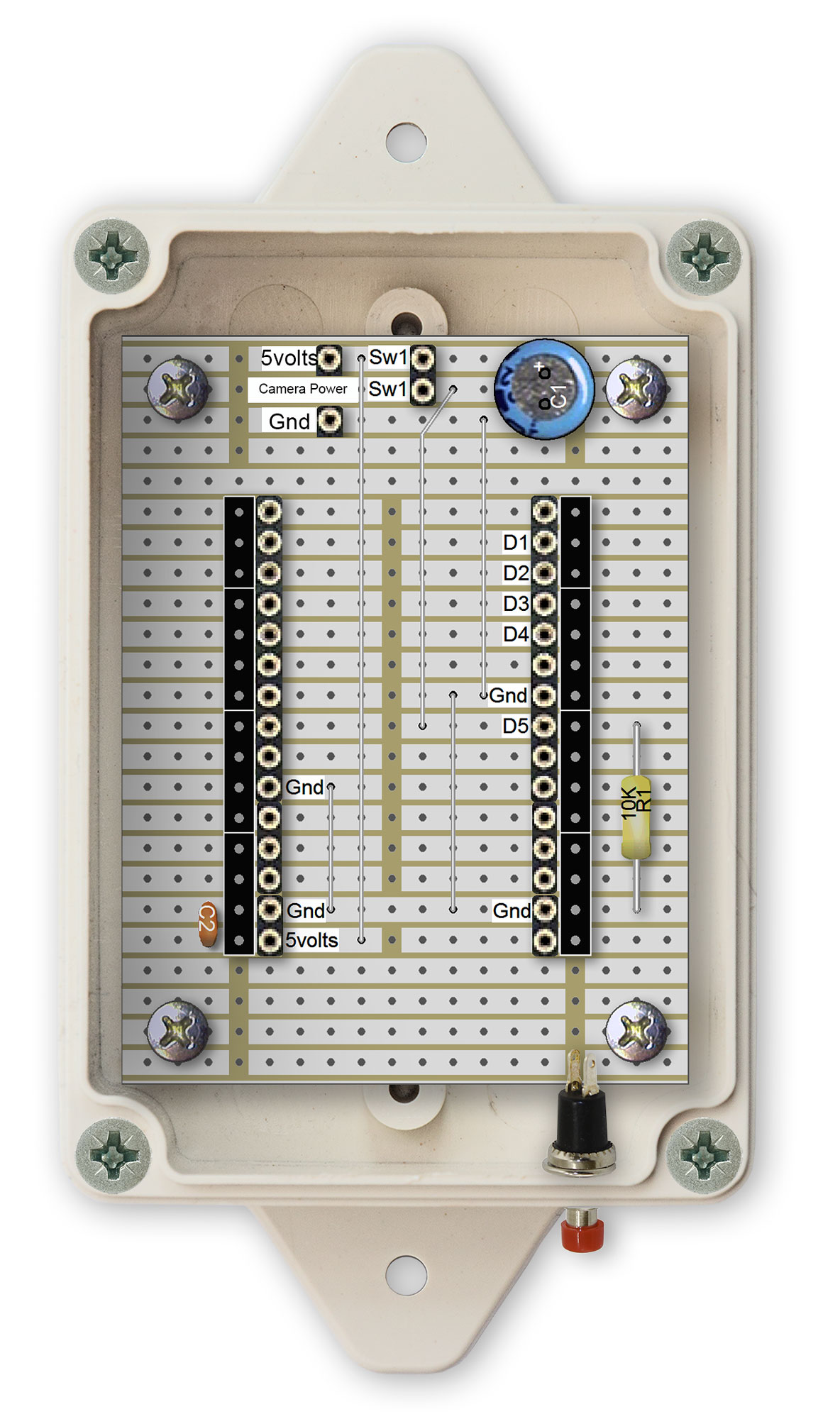
The ESP8266 module is housed in the 2nd box
2nd box with ESP8266 module removed to show Vero Board layout
Click image to see full size version.
Arduino NANO Version
2nd box with NANO
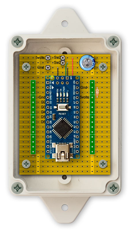
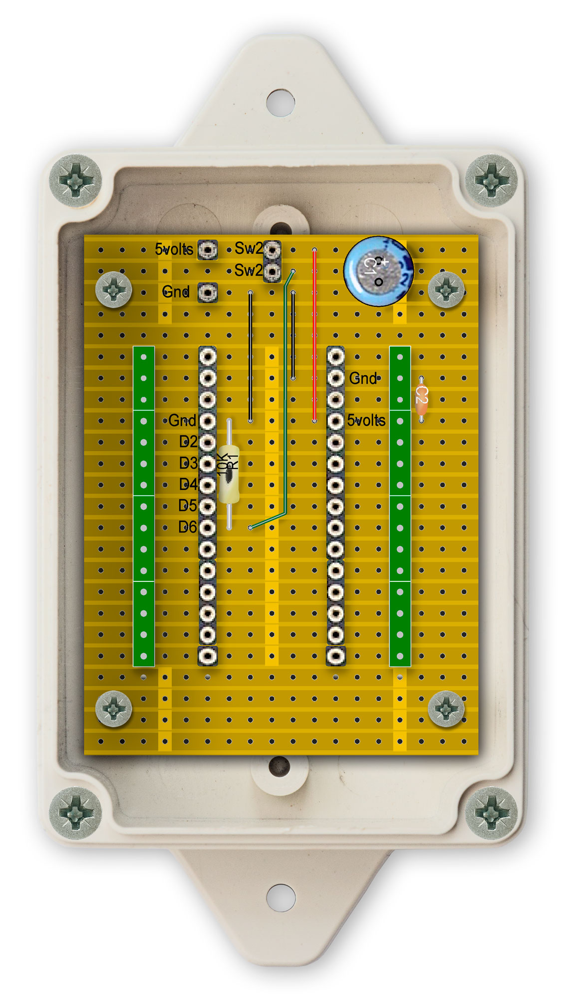
2nd box with NANO removed to show Vero Board layout
Click image to see full size version.
Vero Board Layout of Fuse Board
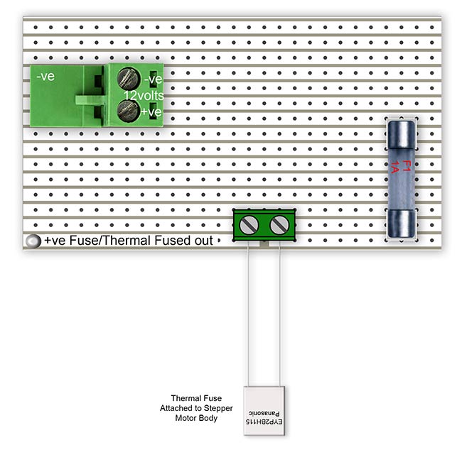
Rear of Fuse Board
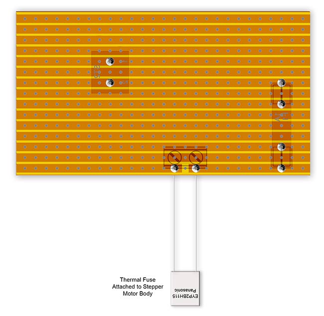
Cutaway below shows position of fuse board above stepper motor.
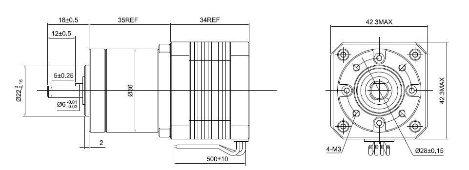
Stepper Motor
This is a short geared NEMA 17 Stepper motor. It has an integrated planetary gearbox with a 26.85:1 gear ratio, the resolution reach 0.067 step angle.
It's a good solution in applications that need very low rotation speeds and/or lots of torque.
I tried an identical motor without the gearbox and it was OK until I added the pet food into the hopper then it jammed.
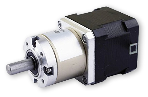
Make sure the mounting bracket has the inner set of drillings if you use this type of motor with a gearbox.
My Stepper Motor Specs
| Manufacturer Part Number | 17HS13-0404S-PG27 |
| Motor Type | Bipolar Stepper |
| Step Angle(W/O Gearbox) | 1.8 |
| Holding Torque | 3Nm |
| Rated Current/phase | 0.4A |
| Phase Resistance | 30ohms |
| Recommended Voltage | 12-24V |
| Inductance | 34mH 20%(1KHz) |
| Gearbox Type | Planetary |
| Gear Ratio(Exact Gear Ratio) | 26 + 103/121 |
| Efficiency | 81% |
| Backlash at No-load | <=1 |
| Max.Permissible Torque | 3Nm(425oz-in) |
| Moment Permissible Torque | 5Nm(708oz-in) |
| Shaft Maximum Axial Load | 50N |
| Shaft Maximum Radial Load | 100N |
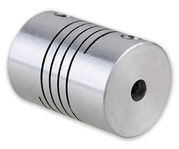
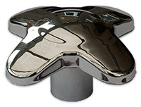
Motor Shaft Coupler
The stepper motor is connected to the feeder d shaft by a motor shaft coupler.
Couplers come is most sizes, my motor has a 6mm shaft and the feeder has a 8mm shaft.
Schematic ESP8266 and NANO
Note Thermal fuse F1. This is attached to the stepper motor body above the coils with wire to form a good physical bond.
Click image to enlarge
Code
The file contains NANO and ESP8266 code in the same file.
Just comment out as required.
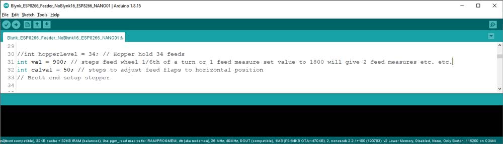
Setting number of feeds
The number of feed measures for each power up of the pet feeder is set to 1.
You can set more than one feed measure by changing the code.
Line 31 of the code sets the value of one measure e.g. val = 900. To make the feeder do two measures for each power up change to val = 1800 etc. etc.