
Section Top Video Decode Anim Credits DCF77 Signal DCF77 Weather Leap Second Control Panel Analyzer Serial Monitor DCF77 Filter Construction Atmega 328 Lolin D32 Pro Modules Vero Board Schematic Code
TFT DCF77 Analyzer with TFT Serial Monitor & DCF77 Filter

This is a TFT version of Erik de Ruiter's DCF77 Analyzer Clock. The DCF77 signal including weather is decoded and displayed on a 2.8" ILI9341 TFT via a Lolin D32 Pro v2 board.
Coded by tobozo it also includes full weather data decode city by city.
I have added a serial monitor using an Atmega 328 with a 2nd TFT alongside the Analyzer TFT to show the weather decode live.
A modified Udo Klein DCF77 Super Filter is also added via a 2nd Atmega 328 to clean up very noisy signals.
The DCF77 Super Filter serial output can also be displayed on the Serial monitor if required.
Video
Typical DCF77 Analyzer outputs.

Features
DCF77 Signal Displayed on a 2.8" TFT Screen second by second
Decoded Weather Data is displayed on a 2nd TFT Screen
DCF77 Signal can be filtered/error corrected
DCF77 filter level can be set to low (filtered) or high (fully synthesized)
DCF77 filter info can be displayed on the 2nd TFT screen if required
Serial Monitor can be used to monitor external sources
Serial monitor baud rate can be set to 5 different values
A full minute of DCF77 Data being received

Credits
There are three distinct parts to this project.
DCF77 TFT Analyzer
TFT Serial Monitor
DCF77 Super Filter
All the parts can be built stand alone as required.
DCF77 TFT Analyzer Copyright (c) 2018 tobozo
I had an initial version of the tobozo's DCF77 TFT Analyzer working on a TTGO TS v1.2.
This worked fine but I found the display too small.

I wanted to use a 320x240 2.2" or 2.8" TFT display and tobozo kindly provided me with some prototype code and helped me
get it working on a 2.8" 320x240 ILI9341 TFT display.

I have modified the prototype code in places to make it fit the larger display correctly.
The serial output to display the Meteo Data was designed for a full screen serial monitor so I have also modified this to fit on a 2.8" TFT display.

TFT Serial Monitor by Alan Senior
The original sketch was included as an example in the Adafruit_ILI9341_AS library.
I have modified the code so the baud rate can be modified on startup.
Switches are included so the DCF77 decode, Super Filter or an external serial input can be displayed.
If switched to the external input with nothing connected this will pause the last serial input.
This is useful when viewing the Filter output as it changes once per second.

DCF77 Super Filter by Udo Klein
When switched on the Udo Klein's Super
Filter actively processes the incoming DCF77 signal
from the
antenna/receiver. After a few minutes of sampling the DCF77 signal the Super
Filter will predict the DCF77 signal and use this
to determine if the
incoming signal contains any errors. The Super Filter will then synthesize a
corrected DCF77 signal even if the signal is absent.

I have modified the Super Filter Code to
add extra monitor LEDs, there are now 10 in total.
In order to do this I have removed 4 modes from
the filter just leaving synthesized and inverted synthesized.
Detailed DCF77 Signal and Filter information (I have changed what's output and the format) can be viewed on the TFT Monitor

The DCF77 Signal
DCF77 is a German long wave time signal and is transmitted from Mainflingen
Germany, about 25 km south-east of Frankfurt am Main.
The DCF77 signal is an amplitude-modulated, pulse-width coded 1 bit/s data
signal. As each bit is transmitted every second it makes it a very visible time
signal for displaying on the TFT display.
Map showing the distance from the DCF77 transmitter in Germany.

In Kenley UK we are able to get very good DCF77 reception. I monitor this 24/7 and show live charts see below so you can see if your signal interference is similar to mine.
Live charts showing DCF77 signal reception in Kenley UK
1 = all 60 bits of data received with no errors in the last minute. 0 = 1 or more data bits received in the last minute had an error.
DCF77 is controlled by the Physikalisch-Technische Bundesanstalt (PTB),
Germany's national physics laboratory and transmits 24/7.
Most service
interruptions are short-term disconnections of under two minutes. Longer lasting
transmission service interruptions are generally caused by strong winds,
freezing rain or snow induced T-antenna movement.
This manifests itself in electrical detuning of the antenna resonance circuit
and hence a measurable phase modulation of the received signal. When the
maladjustment is too large, the transmitter is taken out of service temporarily.
Over a year this will typically be a few hours.
The time code sent is either in Coordinated Universal Time (UTC)+1 or UTC+2 depending on daylight saving time.
The time is represented in binary-coded decimal. It represents civil time, including summer time adjustments.
The time transmitted is the time of the following minute; e.g. during December 31 23:59, the transmitted time encodes January 1 00:00.
The chart below shows the makeup of the DCF77 time code transmitted at 1
pulse per second over 60 seconds

This chart shows details of the transmitted code

DCF77 Weather Data
Encrypted weather data is transmitted, alongside the time and date information, from the DCF77 transmitter.
In each minute there are 14 bits which are sent and one weather message consists of three consecutive minutes of 14 bits of weather data. In total 42 bits are used.
Note bits 1 and 8 from the first minute are not used.
In addition there are 40 bits needed derived from the time signal itself, this acts as the cypher.

The 42 bits of data are collected from bits 1 to 14 over 3 minutes.

Serial monitor showing decoded weather info after 3 consecutive error free minute decodes.
There are 480 of these pages in a day making up the weather/forecast for the DCF77 area
14 encrypted weather bits are transmitted every minutes making 42 bits in total
The transmission starts again after 24 hours at 10 p.m. UTC with region 0.
A total of 90 regions in Europe are supplied with weather data.
60 with a 4-day forecast and 30 with a two-day forecast. This results in the
following sequence:
Start at 10 p.m. UTC with
region 0 - 59 maximum
values 1st day (today)
region 0 - 59 minimum values 1st day (today)
region 0 - 59 maximum values 2nd day (tomorrow)
region 0 - 59 minimum
values 2nd day (tomorrow)
region 0 - 59 maximum values 3rd day
region 0
- 59 minimum values 3rd day
region 0 - 59 maximum values 4th day
region
0 - 59 Weather anomalies and wind data for the 4th day.
Since no minimum
values are transmitted for the 4th day, one uses the capacities freed up for
region 60 - 89 maximum values 1st day
region 60 - 89 maximum values 2nd
day
It should be noted that the data for two regions are transmitted in
the last 60 data records transmitted.
Weather Code Times in London note shown in CET take an hour off for GMT
| Transmission Minute CET | Area Code | City/Country | 4 Day Forecast Day = | 4 Day Forecast Night = |
| 00:56 | 18 | London (Great Britain) | 1 | |
| 03:56 | 18 | London (Great Britain) | 1 | |
| 06:56 | 18 | London (Great Britain) | 2 | |
| 09:56 | 18 | London (Great Britain) | 2 | |
| 12:56 | 18 | London (Great Britain) | 3 | |
| 15:56 | 18 | London (Great Britain) | 3 | |
| 18:56 | 18 | London (Great Britain) | 4 | |
| 21:56 | 18 | London (Great Britain) | 4 |
Regions
| Region No. | Region/City | Region No. | Region/City | Region No. | Region/City | Region No. | Region/City | Region No. | Region/City | Region No. | Region/City |
| 0 | FRANCE Bordeaux | 15 | BRITAIN Swansea | 30 | GERMANY Erfurt | 45 | GERMANY Strasbourg | 60 | ITALY Napoli | 75 | IRELAND Galway |
| 1 | FRANCE la Rochelle | 16 | BRITAIN Manchester | 31 | SWITZERLAND Lausanne | 46 | AUSTRIA Klagenfurt | 61 | ITALY Ancona | 76 | IRELAND Dublin |
| 2 | FRANCE Paris | 17 | FRANCE le Havre | 32 | SWITZERLAND Zuerich | 47 | AUSTRIA Innsbruck | 62 | ITALY Bari | 77 | BRITAIN Glasgow |
| 3 | FRANCE Brest | 18 | BRITAIN London | 33 | SWITZERLAND Adelboden | 48 | AUSTRIA Salzburg | 63 | HUNGARY Budapest | 78 | NORWAY Stavanger |
| 4 | FRANCE Clermont | 19 | GERMANY Bremerhaven | 34 | SWITZERLAND Sion | 49 | AUSTRIA Wien | 64 | SPAIN Madrid | 79 | NORWAY Trondheim |
| 5 | FRANCE Beziers | 20 | DENMARK Herning | 35 | SWITZERLAND Glarus | 50 | CZECH REPUBLIC Praha | 65 | SPAIN Bilbao | 80 | SWEDEN Sundsvall |
| 6 | BELGIUM Bruxelles | 21 | DENMARK Arhus | 36 | SWITZERLAND Davos | 51 | CZECH REPUBLIC Decin | 66 | ITALY Palermo | 81 | POLAND Gdansk |
| 7 | FRANCE Dijon | 22 | GERMANY Hannover | 37 | GERMANY Kassel | 52 | GERMANY Berlin | 67 | SPAIN Palma | 82 | POLAND Warszawa |
| 8 | FRANCE Marseille | 23 | DENMARK Copenhagen | 38 | SWITZERLAND Locarno | 53 | SWEDEN Gothenburg | 68 | SPAIN Valencia | 83 | POLAND Krakow |
| 9 | FRANCE Lyon | 24 | GERMANY Rostock | 39 | ITALY Sestriere | 54 | SWEDEN Stockholm | 69 | SPAIN Barcelona | 84 | SWEDEN Umea |
| 10 | FRANCE Grenoble | 25 | GERMANY Ingolstadt | 40 | ITALY Milano | 55 | SWEDEN Kalmar | 70 | AN Andorra | 85 | SWEDEN Oestersund |
| 11 | SWITZERLAND La Chaux | 26 | GERMANY Muenchen | 41 | ITALY Roma | 56 | SWEDEN Joenkoeping | 71 | SPAIN Sevilla | 86 | SWITZERLAND Samedan |
| 12 | GERMANY Frankfurt/M | 27 | ITALY Bolzano | 42 | NETHERLANDS Amsterdam | 57 | GERMANY Donauechingen | 72 | SPAIN Lissabon | 87 | CROATIA Zagreb |
| 13 | GERMANY Trier | 28 | GERMANY Nuernberg | 43 | ITALY Genova | 58 | NORWAY Oslo | 73 | ITALY Sassari | 88 | SWITZERLAND Zermatt |
| 14 | GERMANY Duisburg | 29 | GERMANY Leipzig | 44 | ITALY Venezia | 59 | GERMANY Stuttgart | 74 | SPAIN Gijon | 89 | CROATIA Split |

Leap Second
A leap second is a one-second adjustment that is occasionally applied to
Coordinated Universal Time (UTC), to accommodate the difference between precise
time (as measured by atomic clocks) and imprecise observed solar time (known as
UT1
and which varies due to irregularities and long-term slowdown in the Earth's
rotation). The UTC time standard, widely used for international timekeeping and
as the reference for civil time in most countries,
uses precise atomic time and consequently would run ahead of observed solar time
unless it is reset to UT1 as needed.The leap second facility exists to provide
this adjustment.
Because the Earth's rotation speed varies in response to climatic and geological
events,UTC leap seconds are irregularly spaced and unpredictable. Insertion of
each UTC leap second is usually decided about six months in advance by the
International Earth Rotation and Reference Systems Service (IERS),
to ensure that the difference between the UTC and UT1 readings will never exceed
0.9 seconds.
Insertion of Leap Seconds
The scheduling of leap seconds was initially delegated to the Bureau
International de l'Heure (BIH), but passed to the International Earth Rotation
and Reference Systems Service (IERS) on January 1, 1988. IERS usually decides to
apply a leap second whenever
the difference between UTC and UT1 approaches 0.6 s,in order to keep the
difference between UTC and UT1 from exceeding 0.9 s.
The UTC standard allows leap seconds to be applied at the end of any UTC month,
with first preference to June and December and second preference to March and
September. As of January 2017, all of them have been inserted at the end of
either June 30 or December 31.
IERS publishes announcements every six months, whether leap seconds are to occur
or not, in its "Bulletin C". Such announcements are typically published well in
advance of each possible leap second date – usually in early January for June 30
and in early July for December 31.
Some time signal broadcasts give voice announcements of an impending leap
second.
Leap Seconds since 1972
| Year | 1972 | 1973 | 1974 | 1975 | 1976 | 1977 | 1978 | 1979 | 1980 | 1981 | 1982 | 1983 | 1984 | 1985 | 1986 | 1987 | 1988 | 1989 | 1990 | 1991 | 1992 | 1993 | 1994 | 1995 | 1996 | 1997 | 1998 | 1999 | 2000 | 2001 | 2002 | 2003 | 2004 | 2005 | 2006 | 2007 | 2008 | 2009 | 2010 | 2011 | 2012 | 2013 | 2014 | 2015 | 2016 | 2017 | 2018 | 2019 | 2020 | Year | Total | |
| Jun-30 | 1 | 0 | 0 | 0 | 0 | 0 | 0 | 0 | 0 | 1 | 1 | 1 | 0 | 1 | 0 | 0 | 0 | 0 | 0 | 0 | 1 | 1 | 1 | 0 | 0 | 1 | 0 | 0 | 0 | 0 | 0 | 0 | 0 | 0 | 0 | 0 | 0 | 0 | 0 | 0 | 1 | 0 | 0 | 1 | 0 | 0 | 0 | 0 | 0 | Jun-30 | 11 | 27 |
| Dec-31 | 1 | 1 | 1 | 1 | 1 | 1 | 1 | 1 | 0 | 0 | 0 | 0 | 0 | 0 | 0 | 1 | 0 | 1 | 1 | 0 | 0 | 0 | 0 | 1 | 0 | 0 | 1 | 0 | 0 | 0 | 0 | 0 | 0 | 1 | 0 | 0 | 1 | 0 | 0 | 0 | 0 | 0 | 0 | 0 | 1 | 0 | 0 | 0 | 0 | Dec-31 | 16 | |
Between 1972 and 2020, a leap second has been inserted about every 21 months, on
average.
However, the spacing is quite irregular and apparently increasing: there were no
leap seconds in the six-year interval between January 1, 1999 and December 31,
2004,but there were nine leap seconds in the eight years 1972–1979.
Unlike leap days, which begin after February 28 23:59:59 local time,[a] UTC leap
seconds occur simultaneously worldwide; for example, the leap second on December
31, 2005 23:59:60 UTC was December 31, 2005 18:59:60 (6:59:60 p.m.) in U.S.
Eastern Standard Time and January 1 and January 1 00:59:60 CET Central European
Time.
DCF77 Leap Second
The Leap Second is announced in the DCF77 signal 1 hour before the leap second
is due. This is signaled by Bit 19 of the DCF77 signal being set to 1 an hour
before the leap second.
Therefore DCF77 clocks will receive 60 of these before the leap second bit is
sent.
The leap second bit (always 0) is sent on the 60th bit and is followed by the
normal minute marker.
This means that minute will last for 61 seconds rather than 60.
Below looped animation -leap second being received on my DCF77 Analyzer
The inner ring shows the incoming DCF77 signal in real time (Grey is 0 and Red
is 1).
The inner ring shows the DCF77 buffer and is labeled 0 to 59 for the 60 seconds
of the minute being received.
Normally buffer 59 is blank as per the corresponding mark on the outer ring for
the last minute. A leap second is inserted here shown by an extra 0 on buffer
59.
The time is the time on the RTC and this resets itself as normal to 01:00:00
after 59 seconds but the buffer store inner ring is not reset nor is the current
time buffer store updated.
The Analyzer picks up the extra leap second bit then resets the whole buffer
store and updates the current buffer outer ring with the new time and resets the
RTC to 01:00:00 again 1 second later.
The RTC is now 1 second slower after the insertion of the Leap Second

This image shows the leap second as an extra 0 bit on the inner ring buffer
store.
The RTC has reset to 01:00:00.
"Leap Second Inserted" warning appears below the time.
The time & date of the last leap second is displayed on the TFT.


Looped animation showing the leap second detail and how it makes the DCF77
controlled clock lose 1 second.

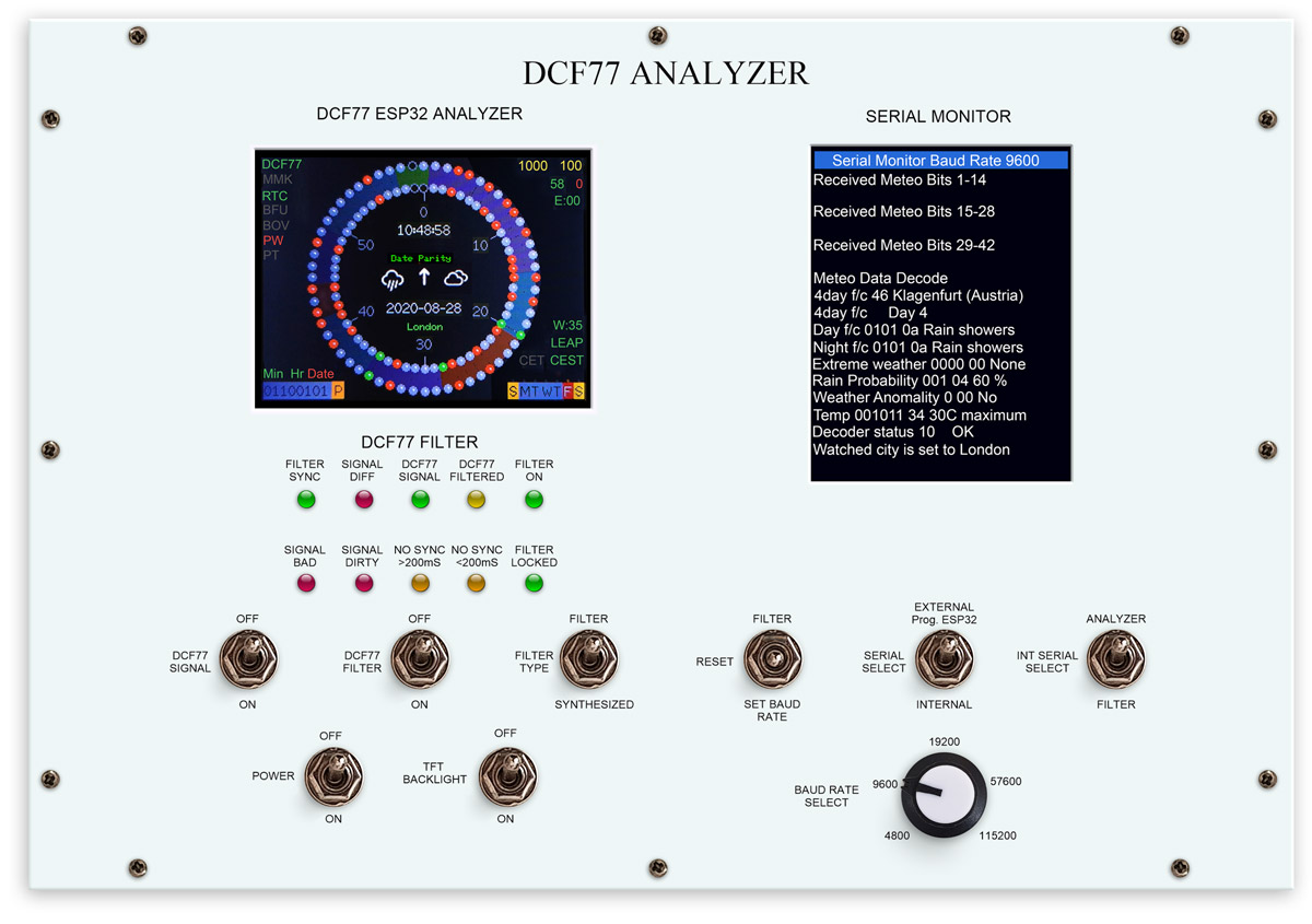
Main TFT Analyzer Control Panel
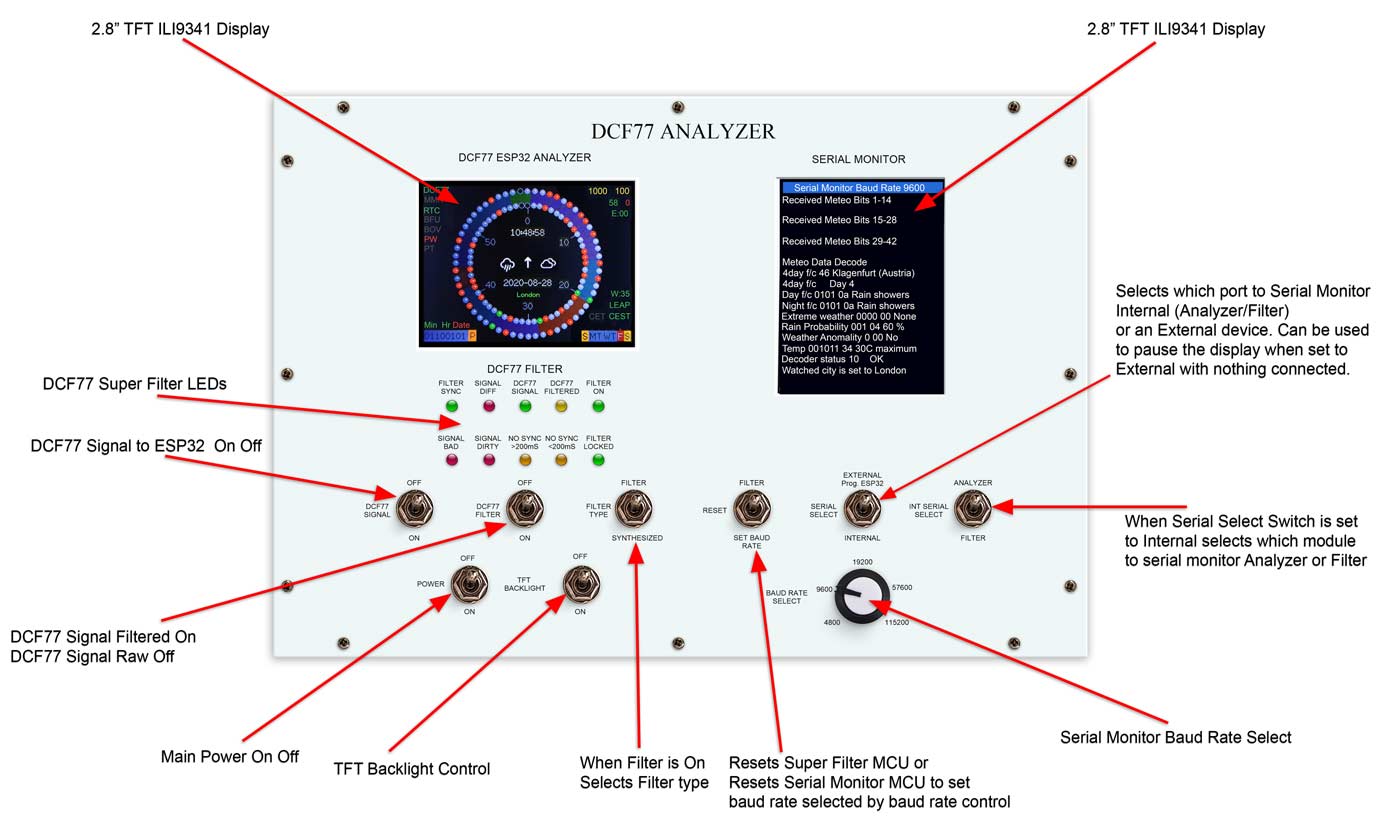
The control panel is split into four sections DCF77 ESP32 Analyzer, DCF77 Filter, Power/Display & Serial Monitor

The DCF77 ESP32 Analyzer contains the main TFT display showing the DCF77 signal and decoding.
The DCF77 Filter contains the filter LEDs and filter control switches.
The Power/Display section has common controls for main power and TFT display backlights On or Off.
The Serial Monitor Section contains the serial TFT display and control switches for the serial monitor.
DCF77 TFT Analyzer Detail tobozo
Modelled on Eric The DCF77 analyzer works on a ILI9341 TFT via a Lolin D32 Pro v2 board.
It seems to work on all 2.2" ILI9341 TFT displays but for some reason only works on 2.8" ILI9341 touch displays.
tobozo has created a branch off the main esp-DCF32_Analyzer_Clock on github for this version.
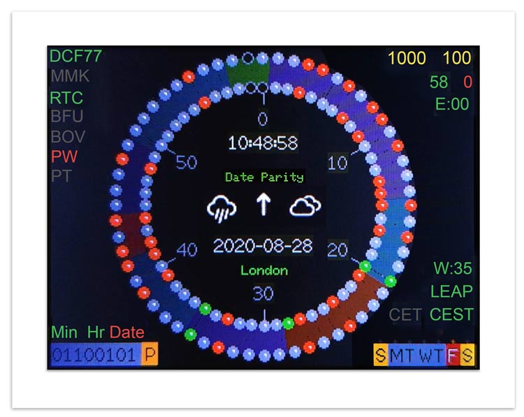
Emulating Erik de Ruiter's DCF77 Analyzer Clock the analyzer displays the DCF77 time code on 2 rings of 60 "LEDs" on the TFT display.
The inner ring shows the live time code for the next minute as it is received
and the outer ring shows the current time as long as the previous minute was received error free.
Decoded time and date in UTC + 1 or UTC + 2 are shown in the middle of the "LED" rings along with the chosen City and forecast for that city.
Note I have not added adjustments for GMT my home location as I don't use this as a clock just an analyzer.
The animation below shows a full minute of data capture and decode.
The top right of the screen is used to display DCF77 pulse timings and bit information along with the buffer number and number of errors.
The bottom right of the TFT shows the week number, leap year, CET/CEST and also the day of the week.
Top left has DCF77 status indications that change colour depending on their state-Green for good grey no status and red for bad.
There are indicators for DCF77 sync, Minute mark, RTC, Buffer Full, Buffer Overflow, Pulse width error and period of time error.
The bottom left of the display shows the parity for Minutes, Hour and Date in 3 colours.
These are Grey-waiting parity check, Green-parity check OK & Red parity check fail.
Note the very bottom left of the display is not in use and will probably be used for Meteo data info in the future.
The full TFT display on a 2.8" TFT
The illustrations below give further details on the displays


As per the Erik's original analyzer there is an option to do an (LED) test on boot.
Not really necessary on a TFT but a nice touch anyway.
Animation showing the DCF77 Analyzer Boot-up Screen
 |
DCF77 Initial Sync
On boot the time and date are fetched from the RTC.
If this is the first boot the time and date will no be correct as the RTC is set once a complete DCF77 signal is received and decoded.
After this if the analyzer is powered down the RTC stores the time and date.
This animation shows the clock receiving it's initial sync.
The buffers are initial empty and after the analyzer detects a minute mark the received data is loaded into the inner ring once per second.
If no pulse timing or parity errors are found the data is loaded into the outer ring and decoded updating the RTC and filling out the missing data on the display.
The inner ring is emptied ready for the next minutes worth of data.

Note weather data will not be loaded until the weather information for your chosen city is received.
This information of each city is sent over 3 minutes worth of data at various times of the day.
See the DCF77 weather section above for full details.
DCF77 Meteo Data display
Unlike Erik's analyzer tobozo has included full DCF77 weather decoding in his version.
The weather information for your chosen city is displayed on the analyzers TFT screen.
The full weather decode is sent out over the serial port and can be displayed on a serial monitor.
My analyzer has a built in TFT serial monitor display.
Unlike the Arduino serial monitor my TFT monitor is limited in the information it can display.
I have modified the serial printing so all the data for each city fits onto my TFT display.
The data for each city is received over three consecutive minutes in 14 bit sections.
During a 24hr period there will be up to 7 separate TFT "pages of data sent".
Each page contains different weather info for each city and there are 480 pages sent containing data for 90 cities, 60 with a 4-day forecast and 30 with a two-day forecast.
The illustration below shows the weather page for Klagenfurt in Austria and is built up over 3 minutes.
Every minute the received "meteo" bits are checked and if OK the line Received Meteo Bits x-xx ae shown.
If the received meteo bits contain errors they will be rejected and the line for that data will be missing.
If the analyzer does not receive all these bits 1-14, 15-28 & 29-42 over the three minute period the weather page can't be decoded and won't be displayed.
TFT Serial Monitor Detail
This sketch uses the built in hardware scrolling feature of the ILI9341 chip,
this takes the processing burden off the Arduino AVR microcontroller and means
that the display can keep up with serial text messages at 9600 baud.
The
ILI9341 and GFX libraries been optimised for speed, some of the speed enhancing
features use direct PORT access to the ATmega328 registers so it is important to
use an Arduino board based on that processor chip.
These speed improvements means that characters in the proportional font 2 can be printed to the screen at more than 1000 characters per second.
The original sketch worked only at 9600 baud so I have added an option in the start menu to set the baud rate to 5 different values.

The rate required is set on the rotary control and then the Serial Monitor is reset by selecting "SET BAUD RATE" on the "RESET" non latching toggle switch so this new rate is loaded.
Once restarted the new board rate is shown on the top of the TFT.

The serial terminal can also read the serial output from external sources by selecting "EXTERNAL Prog. ESP32" on the "SERIAL SELECT" switch.
With the switch in this position the external serial port on the back on the DCF77 Analyzer is selected.
The external source's 0v should be connected to 0v of the Analyzer.
With the switch in this position and no external source selected anything that was connected on the internal port is "freeze framed".
This is useful for reading the 1 second output from the Filter as it scrolls every second.

When set to "INTERNAL" the "INT SERIAL SELECT" latching switch becomes live.
When set to "ANALYZER" the serial port output of the TFT analyzer is displayed on the TFT display.
When set to "FILTER" the serial port output of the DCF77 Filter is displayed on the TFT display.

Arduino Serial Buffer Modification
I have modified the serial buffer on the serial monitor from 64 to 1024 so it should be able to handle faster baud rates.
The serial monitor UNO does nothing else but print out what's on the serial port so it has memory to spare.
To do this on my Arduino version 1.8.5 go to the Arduino core code directory and copy the Arduino folder.

My folder is in C:\Program Files (x86)\arduino-1.8.5\hardware\arduino\avr\cores
Paste the whole Arduino folder and then rename it to arduino_1024_serialbuf

Open this new folder C:\Program Files\arduino-1.0.1\hardware\arduino\cores\arduino_1024_serialbuf
and then look for the file USBAPI.h.
Open this folder in an editor.
Look for these lines
#ifndef SERIAL_BUFFER_SIZE
#if ((RAMEND - RAMSTART) < 1023)
#define SERIAL_BUFFER_SIZE 16
#else
#define SERIAL_BUFFER_SIZE 64
#endif
#endif
#if (SERIAL_BUFFER_SIZE>256)
#error Please lower the CDC Buffer size
#endif
Change buffer size the line in red to 1024.
You now have the following.
#ifndef SERIAL_BUFFER_SIZE
#if ((RAMEND - RAMSTART) < 1023)
#define SERIAL_BUFFER_SIZE 16
#else
#define SERIAL_BUFFER_SIZE 1024
#endif
#endif
#if (SERIAL_BUFFER_SIZE>256)
#error Please lower the CDC Buffer size
#endif
Save the file.
Next I modified the Boards.txt file.
My files was in the avr folder here
C:\Program Files (x86)\arduino-1.8.5\hardware\arduino\avr
Locate the UNO board in the file see below
##############################################################
uno.name=Arduino/Genuino Uno
uno.vid.0=0x2341
uno.pid.0=0x0043
uno.vid.1=0x2341
uno.pid.1=0x0001
uno.vid.2=0x2A03
uno.pid.2=0x0043
uno.vid.3=0x2341
uno.pid.3=0x0243
uno.upload.tool=avrdude
uno.upload.protocol=arduino
uno.upload.maximum_size=32256
uno.upload.maximum_data_size=2048
uno.upload.speed=115200
uno.bootloader.tool=avrdude
uno.bootloader.low_fuses=0xFF
uno.bootloader.high_fuses=0xDE
uno.bootloader.extended_fuses=0xFD
uno.bootloader.unlock_bits=0x3F
uno.bootloader.lock_bits=0x0F
uno.bootloader.file=optiboot/optiboot_atmega328.hex
uno.build.mcu=atmega328p
uno.build.f_cpu=16000000L
uno.build.board=AVR_UNO
uno.build.core=arduino
uno.build.variant=standard
##############################################################
Copy the section of txt and paste it below.
Modify the txt you have just pasted as below.
1024 has been added after the uno
on each line and the build.core line has the arduino replaced by
arduino_1024_serialbuf
##############################################################
Uno1024.name=Arduino Uno (1024 Serial Buffer)
uno1024.vid.0=0x2341
uno1024.pid.0=0x0043
uno1024.vid.1=0x2341
uno1024.pid.1=0x0001
uno1024.vid.2=0x2A03
uno1024.pid.2=0x0043
uno1024.vid.3=0x2341
uno1024.pid.3=0x0243
uno1024.upload.tool=avrdude
uno1024.upload.protocol=arduino
uno1024.upload.maximum_size=32256
uno1024.upload.maximum_data_size=2048
uno1024.upload.speed=115200
uno1024.bootloader.tool=avrdude
uno1024.bootloader.low_fuses=0xFF
uno1024.bootloader.high_fuses=0xDE
uno1024.bootloader.extended_fuses=0xFD
uno1024.bootloader.unlock_bits=0x3F
uno1024.bootloader.lock_bits=0x0F
uno1024.bootloader.file=optiboot/optiboot_atmega328.hex
uno1024.build.mcu=atmega328p
uno1024.build.f_cpu=16000000L
uno1024.build.board=AVR_UNO
uno1024.build.core=arduino_1024_serialbuf
##############################################################

Serial monitor showing decoded weather info after 3 consecutive error free minute decodes.
There are 480 of these pages in a day making up the weather/forecast for the DCF77 area
14 encrypted weather bits are transmitted every minutes making 42 bits in total
The transmission starts again after 24 hours at 10 p.m. UTC with region 0.
A total of 90 regions in Europe are supplied with weather data.
60 with a 4-day forecast and 30 with a two-day forecast. This results in the
following sequence:
Start at 10 p.m. UTC with
region 0 - 59 maximum
values 1st day (today)
region 0 - 59 minimum
values 1st day (today)
region 0 - 59 maximum values 2nd day (tomorrow)
region 0 - 59 minimum
values 2nd day (tomorrow)
Region 0 - 59 maximum values 3rd day
Region 0
- 59 minimum
values 3rd day Region 0 - 59 maximum values 4th day
Region
0 - 59 Weather anomalies and wind data for the 4th day.
Since no minimum
values are transmitted for the 4th day, one uses the capacities freed up for
region 60 - 89 maximum values 1st day
region 60 - 89 maximum values 2nd
day
It should be noted that the data for two regions are transmitted in
the last 60 data records transmitted.
DCF77 Super Filter Detail

The Super Filter uses an Atmega 328 (UNO) IC to process the DCF77 signal.
The incoming DCF77 signal is monitored on the "DCF77 SIGNAL" led.
The filtered signal is monitored on the "DCF77 FILTERED" led. With a noiseless signal the "DCF77 SIGNAL" & "DCF77 FILTERED" led will flash in unison.
Any slight difference is shown on the "SIGNAL DIFF" led.
With a noisy DCF77 signal the "DCF77 SIGNAL" will flash with the noise on the signal but the filtered LED once the filter us in sync will flash correctly as the filter knows what pulse to expect next and will "SYNTHESIZE" it if not present.
Below noisy signal. Note the "DCF77 FILTERED" led pulses as normal despite the noise.

LED Function Chart
| Name | Description |
| Filter On | lights when the DCF77 Source switch is set to FILTER and means the Super Filter is decoding and synthesizing the DCF77 signal |
| DCF77 Filtered | the DCF77 Synthesized signal coming out from the Super Filter |
| DCF77 Signal | the DCF77 signal coming direct from the DCF77 receiver with no filter applied |
| Signal Difference | the difference between the incoming DCF77 signal and the Synthesized signal. In normal operation this will flash as the received signal shape is often slightly “wider” than the synthesized signal. |
| Filter Synchronized | best possible quality, clock is 100% synced |
| Filter Locked | clock driven by accurate phase, time is accurate but not all decoder stages have sufficient quality for sync |
| Sync Lost <200mS | clock was once synced, inaccuracy below 200 ms, may re-lock if a valid phase is detected |
| Sync Lost >200mS | clock was once synced but now may deviate more than 200 ms, must not re-lock if valid phase is detected |
| Signal Dirty | time data available but unreliable |
| Signal Bad | waiting for good enough signal |
Details
Filter Synchronized - Timing is completely locked to DCF77 and
the data is most up to date.
Filter Locked - If the quality factor of the
decoder stages drops but the quality factor of the phase decoder stays high
enough the clock will transition into the state locked.
In this state it
is still phase locked to DCF77 but it may become out of sync by a second but
only if a leap second is transmitted.
Sync Lost <200mS - This indicates
that the quality factor of the decoder stage and the quality factor of the phase
decoder have dropped. In this state the timer relies on the quartz crystal
timings and the clock will slowly drift out of phase with the DCF77 signal. This
is a warning that the clock may be running slightly out of sync.
Sync
Lost >200mS - Once the clock has started to drift out of phase for more than a
set period of time (depending on the tuned accuracy of the quartz crystal) then
this LED will light
Main Panel with the serial monitor switched to monitor the filter that outputs every second

DCF77 Filter Switches
Note in any switch position the DCF77 signal is always connected to the Filter.
This alows the Filter to always learn the signal and also tune the Quartz crystal.
This switch turns the DCF77 signal On or off

This switch turns the DCF77 Filter on or Off

This switch selects the filter type

Filtered Output – If the clock is at least in state “locked” the output is synthesized and thus 100% clean.
The phase will be spot on but it might leap for 1s at unexpected times if can not properly decode the leap second announcement bit while a leap second is actually scheduled.
In less than “locked” states it will pass the signal through. This is the most defensive modes which provides least filtering. If your DCF77 signal is not total crap it may be more than sufficient.
Synthesized Output – This is the most aggressive filter mode.
After its initial sync it will synthesize no matter what the internal state is.
However beware: if you do not evaluate the diff pin you will never know that it may be running “free” and thus drifting out of sync slowly.
Of course if the signal is reasonable every once in a while it will re-sync though.
Filter starting up.
Signal is shown as "SIGNAL BAD" as the filter is waiting to sync to the signal.
During this time if a noisy signal is received the filter will not correct it.
The noise is passed to the DCF77 decoder as shown by the DCF77 Signal and DCF77 Filtered LEDs flashing out of time every now and then as noise is received.
It will however keep learning looking for repeating patterns in the signal even though the signal is noisy.
As the filter learns the signal the "Signal Bad" LED will go out and the "Signal Dirty" LED will light.
This indicates that time data is available but is unreliable.
This is flowed by the "Filter Locked" LED.
This indicates that the clock is driven by accurate phase, time is accurate but not all decoder stages have sufficient quality for sync.

Filter in Sync
After a few minutes and it may be many if the signal is very noisy the filter will synchronize indicated by the "Filter Sync" led illuminating.
This indicates best possible quality, clock is 100% synced.
The "Signal Difference" LED will flash to show the difference between the incoming DCF77 signal and the Synthesized signal.
In normal operation this will flash as the received signal shape is often slightly “wider” than the synthesized signal.
Rejecting a Noisy Signal
Now the filter is in sync the filter knows what pulse to expect so if any any noise is received the filter synthesizes the correct pulse.
You can see below that the "DCF77 Filtered" LED continues to flash every second despite the DCF77 Signal LED flashing out of time.
An in sync filter will now start to adjust the frequency of the Quartz crystal using the DCF77 signal as a reference.
If the DCF77 signal is lost for many days the clock will stay in sync.
Eventually the quartz crystal will drift and if less than 200mS the "No Sync< 200mS LED will light.
If the crystal drifts more than 200mS then the "No Sync>200mS LED will light.
Once the DCF77 signal is restored the filter will go back into sync again.
Super Filter- on power up the pin connections are displayed

Once powered up the serial display is updated once per second
The meaning is shown in the diagram below.

Control Panel Construction
I used 1mm aluminium sheet to make the panel.

The panel template is printed out from my CAD program onto paper. The TFT holes are cut out with a craft knife and the template is then placed over the blank alluminium sheet.
A marker pen is used to draw around the TFT cut outs onto the alluminium and the hole centers are marked with a center punch through the paper template.

Panel ready for cutting out and drilling

Cutout the holes for the TFTs with a scroll saw/jig saw and drill holes for screws, switches and control knob.

Prime and spray

Printout panel design including centers onto inkjet decal paper and apply to painted panel

Cut away inkjet transfer paper from all holes and cutouts.
Apply two coats of clear varnish.

Completed panel with all parts in place.
DCF77 Analyzer Mounted in a wooden box

Alternative upright wooden box

Box construction
Box is constructed from 9mm plywood.
The box parts are screwed in place.

Cutout for alluminium panel

Alluminium control panel in place

Box painted and lettering decal applied

Box Dimentions

Top view of sides and base

Dimentions

The plywood lid has a section cutout for the controls and displays on the alluminium panel.

Alluminium panel superimposed over the wooden lid showing relative locations of cutouts.
Note the extra cutout for the base of VR1.

Alluminium lid in place.

Atmega 328
Two Atmega 328s (UNOs) are used in this project, 1 for the serial monitor and the other for the DCF77 Super Filter.
The following pins are used.
| Super Filter Pins |
Serial Monitor Pins |
 |
 |
Atmega 328 Pinouts

A Lolin D32 Pro v2 is used for the DCF77 Analyzer
Lolin D32 Pro

Lolin D32 Pro v2 pinout

Lolin D32 Pro v2 schematic
Click image for PDF version

Lolin D32 Pro v2 Pin Table
| Pin | Default Configuration* | Optional Configuration* | Remarks / Prerequisites | Configuration |
| GPIO22 | I2C_DEV(0):SCL | I2C Interfaces | ||
| GPIO21 | I2C_DEV(0):SDA | I2C Interfaces | ||
| GPIO18 | SPI_DEV(0):SCK | SPI Interfaces | ||
| GPIO19 | SPI_DEV(0):MISO | SPI Interfaces | ||
| GPIO23 | SPI_DEV(0):MOSI | SPI Interfaces | ||
| GPIO5 | SPI_DEV(0):CS0 / LED0 | SPI Interfaces | ||
| GPIO4 | SPI_DEV(0):CS1 | SD Card CS | when module sdcard_spi is used | SPI Interfaces |
| GPIO1 | UART_DEV(0):TxD | Console (configuration is fixed) | UART interfaces | |
| GPIO3 | UART_DEV(0):RxD | Console (configuration is fixed) | UART interfaces | |
| GPIO36 | ADC_LINE(0) | ADC Channels | ||
| GPIO39 | ADC_LINE(1) | ADC Channels | ||
| GPIO34 | ADC_LINE(2) | ADC Channels | ||
| GPIO35 | ADC_LINE(3) | VBat measurement (GPIO is not broken out) | ADC Channels | |
| GPIO32 | ADC_LINE(4) | TFT_LED | when TFT is connected | ADC Channels |
| GPIO33 | ADC_LINE(5) | TFT_RESET | when TFT is connected | ADC Channels |
| GPIO25 | DAC_LINE(0) | DAC Channels | ||
| GPIO26 | DAC_LINE(1) | DAC Channels | ||
| GPIO0 | PWM_DEV(0):0 | MRF24J40/ENC28J60 RESET | when module mrf24j40/enc2860 is used | PWM Channels |
| GPIO2 | PWM_DEV(0):1 | MRF24J40/ENC28J60 CS | when module mrf24j40/enc2860 is used | PWM Channels |
| GPIO13 | - | MRF24J40/ENC28J60 INT | when module mrf24j40/enc2860 is used | |
| GPIO15 | - | |||
| GPIO12 | - | TS_CS | when TFT is connected | |
| GPIO14 | - | TFT_CS | when TFT is connected | |
| GPIO27 | - | TFT_DC | when TFT is connected |
Pre-built board and modules
LM2596 Regulator
LM2596 Regulator Module drops the voltage down to 5v.
This is adjusted by the 10K preset resistor on the module.
Adjust this before connecting the Lolin,328s & TFTs to the board.

RTC DS3231 I2C
This module stores the time from the decoded DCF77 signal.
The built in clock has temperature compensation and has battery backup in case of power failure.
Note the RTC module is modified by removing R5 so it takes non rechargeable batteries.


Vero Board Layouts
Note SW3 & SW5 can be omitted from the Vero Board as they are replace by toggle switches on the control panel.


Vero board fully assembled & wired.

Schematic (click image for full size version)
TFT displays and LEDs can be controlled/dimmed off the Lolin D32 Pro AT-LED via a transistor and LDR if required.
The command tft.setBrightness( 0 - 255 ) can be used to set brightness over 256 levels. I have used a similar idea here DCF77 Analyzer Mk2

Testing the DCF77 Analyzer
My
DCF77 Generator digital DCF77 output fed into the DCF77 Analyzer.
The
DCF77 Analyzer displays on both should be exactly the same.

Code
 |
|
|
| TFT Analyzer v26 9600 baud | Serial Monitor v9 | Super Filter v12 |