Home Guestbook HC-SR04 Ultrasonic Stadiometer Version
Section Top Operation How It Works Setup/Example Parts Construction Dot Matrix Displays Micro Switch Schematic Vero Boards 3D Printer Files Code
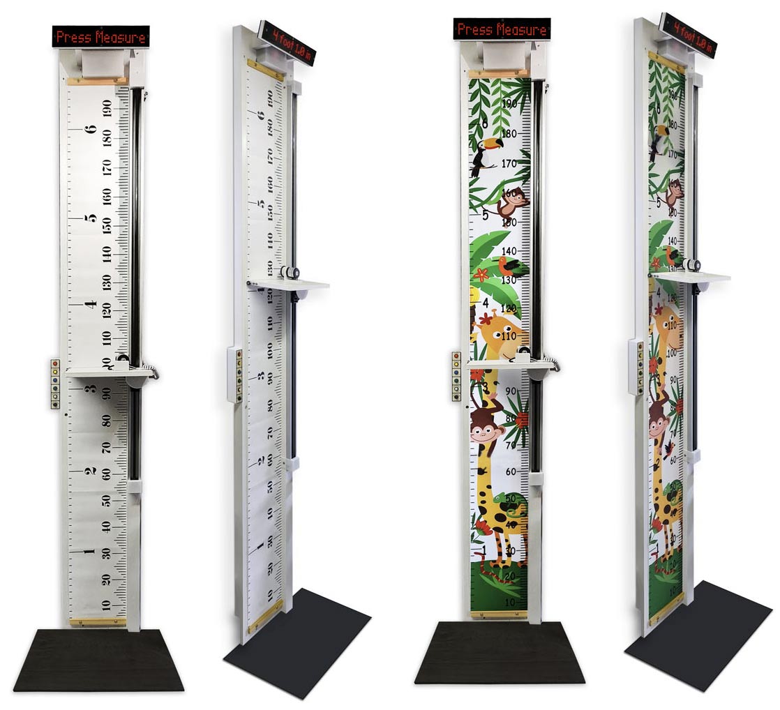
ARDUINO DIGITAL STADIOMETER
QUADRATURE ENCODER VERSION click for HC-SR04 Ultrasonic version
Measure height in Meters/Feet & Inches using an Arduino NANO, Quadrature Rotary Encoder and 8 x MAX2719 Dot Matrix Displays
 |
 |
|
Main Functions Measures height on a conventional commercially available height chart Sliding and locking height bar for accurate readings Height can be recorded on the height chart manually in pen using a 3D printed pen slot on the height bar Digital measurement using a Quadrature Rotary Encoder Display height in metres and feet & inches on a scrolling dot matrix display Matrix display Brightness control  |
Operation
Power on the stadiometer and you will get a message giving instructions on taking a measurement.
To set the encoder at the correct calibrated height move the height bar to the top and hold it until the screen goes blanks and the green LED is illuminated.
Standing on the platform at the base of the stadiometer slide height bar down to your or the person you are measurings head.
The green LED will go out as the height bar is moved and light whenver it stops.
Keeping your feet flat to the platform and the height bar released straighten your body to get you max height.
You will feel the hieght bar move slightly as you adjust to your position correctly.
Once in position lock he height bar in position by pulling the lockng lever down.
Pulling the locking lever down moves the height bar up by around 4mm.
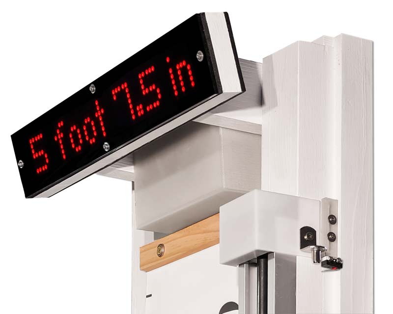
You can now step away from the stadiometer and press the measure button.
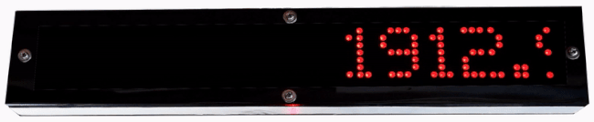
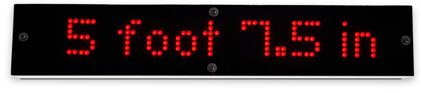
Height in millimeters and feet and inches will be displayed.
To take another reading press the reset button and repeat the above.
If you want to record the measurement on the printed height chart use a marker pen to draw a line using the pen guide fixed to the height bar.
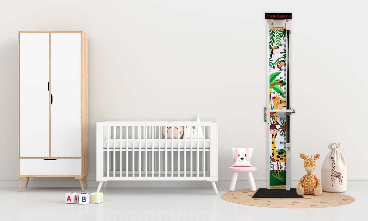
Baby photo created by wuttichai1983 - www.freepik.com
Hand written dates next to marked line from the marker pen guide.
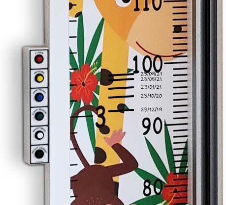
Marker Pen Guide 3D printed and is fixed to the height bar.

How It Works
Quadrature Rotary Encoder

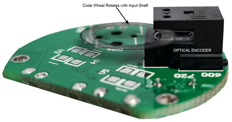
The stadiometer uses a rotary quadrature encoder to record the movement of the height bar from a set position.
As the height bar moves up or down the encoder records the position as a number.
This number is used to caclulate the height.
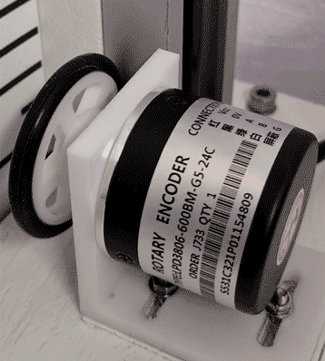
A 3D printed wheel is attached to the encoder and is in contact with the alluminiun side of the guide clamp.
Moving the height bar up and down rotates the wheel connected to the encoder shaft.
A quadrature encoder is an incremental encoder with 2 out-of-phase output channels used in many general automation applications where sensing the direction of movement is required.
Each channel provides a specific number of equally
spaced pulses per revolution (PPR) and the direction of motion is detected
by the phase relationship of one channel leading or trailing the other
channel.
The code disk inside a quadrature encoder contains two tracks usually denoted Channel A and Channel B.
These tracks or channels are coded ninety electrical degrees out of phase, as indicated in the image below, and this is the key design element that will provide the quadrature encoder its functionality.
In applications where direction sensing is required, a controller can determine direction of movement based on the phase relationship between Channels A and B.
This feature is used on the stadiometer as the height bar will be move up or down so it's important to know which way it is travelin.
As illustrated in the example optical encoder animation below, when the encoder is rotating in a clockwise direction its signal will show Channel A leading Channel B, and the reverse will happen when the quadrature encoder rotates counterclockwise.

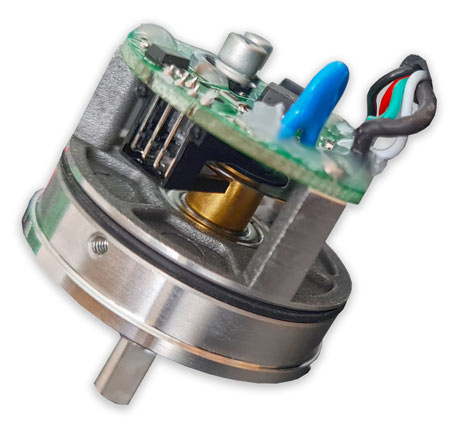
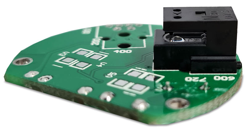
This project uses a Eurobuy 600P/R AB 2-Phases Photoelectric Incremental Rotary Encoder 5V-24V Shaft 6mm
The encoder is housed in a metal case held in position by 3 screws.
The metal case removed showing the internal components.
The code wheel can be seen passing through the optical encoder
Enlarged section of above showing the code wheel passing through the Optical
Encoder. 
Below detail of the optical encoder and PCB. The light source can be seen inside the optical encoder.
The light sensors are housed above.
As above but showing how the code wheel passes through the encoder.
This view though the rear of the encoder body shows the base of the silver shaft with the code wheel fixed to it.
The inset shows some of the 600 lines printed into the code wheel.
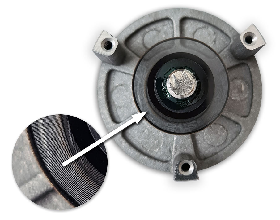
This view shows the input shaft passing through a bearing in the case and fixing to the code wheel.
The threaded metal studs hold the PCB with optical encoder.

The encoder is mounted in a 3D Printed bracket

Adjustment slots allow the encoder wheel to be adjusted against the aluminium guide rail.

The Wheel is 3D printed in 2 parts
1 the wheel hub
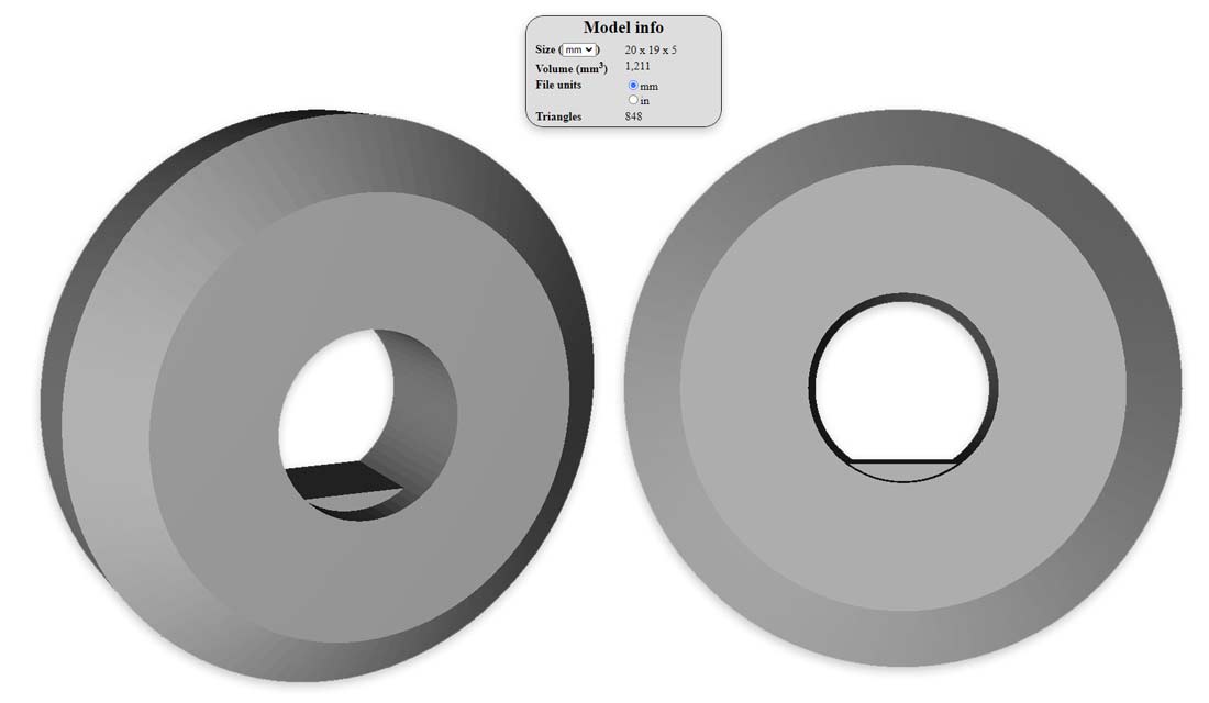
2 the wheel
The large flat side of the hub is glued to the bck of the wheel with super glue. Ensure the wheel runs true before it dries.
The wheel is a friction fit on the encoder shaft.
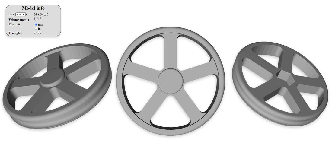
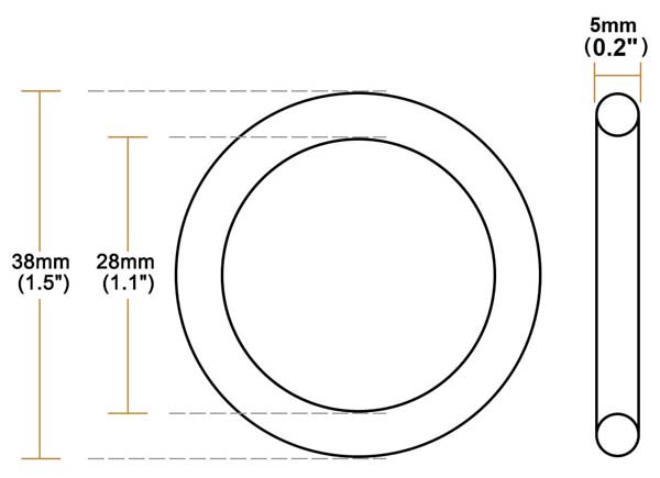
The tyre is an O Ring

 |
Rotary Encoder Stadiometer
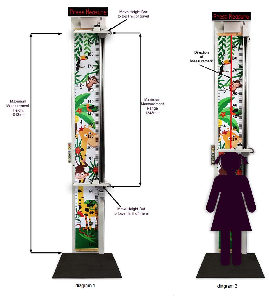
setup & example diagram 1 The rotary encoder is housed in the top height bar and runs agaisnt the guide clamp alluminium channel. Moving the height bar up and down rotates the wheel connected to the encoder shaft and this produces a negative or positive count.
In order to work out the height we need the max distance the height chart will measure, how many times the rotary encoder counts per millimeter and the distance the height bar has travelled.
To work out the rotary encoder counts per millimeter I moved the height bar to the top end stop so the microswitch activated and reset the count.
With the serial monitor conected I slid the height bar down to the minium height and made note of the count 21986.
I measure the range of the stadiometer min to max as 1243mm
Therefore the Rotary Encoder Counts per millimeter will be the min max range divided by the number of counts. Rotary Encoder Counts per millimeter = 1243/21986 Rotary Encoder Counts per millimeter = 0.0565347
The distance the height bar has travelled = number of counts from the rotary encoder x Rotary Encoder Counts per millimeter
This distance is then taken away from the max height of the Stadiometer to give the measure height.
Worked example diagram 2 To start the height bar is moved to the top of the guide to activate the limit microswitch. The count is reset to 0 The subject then steps into the stadiometer and the height bar is slid down to their head. The count records the movement downwards. They adjust their position maximising their height while keeping thier feet flat to the ground. The counts goes up and down as the height bar is moved around as the subject adjusts their position. The slide is locked by pulling the locking lever and the final count is set in the example diagram 2 the count is 15158 The subject can now step out of the stadiometer. The count number 15158 is now multiplied by the counts per millimeter 0.0565347 15158 x 0.0565347 = 857mm The height bar has moved down 857mm. To get the subjects height this is taken away from the height set by the limit switch count reset measured at 1913mm 1913-857 = 1056mm Therefore the subject is 1056mm or 3 foot 5.57 inches Pressing Measure will calculate all this and display it on the LED display.
|
Parts Required
Timber
The structure of the stadiometer is build from re-cycled timber. The main backing is 2 lengths of scrap oak engineered wood flooring joined together and braced with timber batons.
A length of timber fixed to the side provides strength and also provides support for the height bar slide.
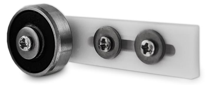
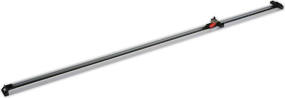
Guide Clamp
I fixed the wooden height bar to an old wood workers guide clamp. This allows the height bar to be slid up and down to rest on the top of the subjects head.
A lever clamps the height bar in place and also lifts the the height bar by 4mm so your subject can walk out of the machine without having to raise the bar.

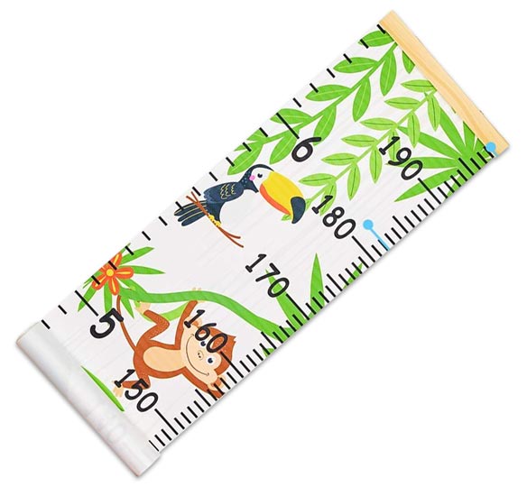
Height Chart
I used a standard height chart from Amazon. There there many types to choose from and come rolled up printed on a plastic canvas.

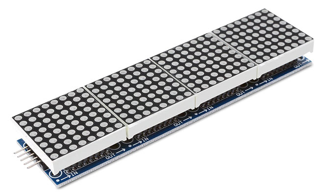
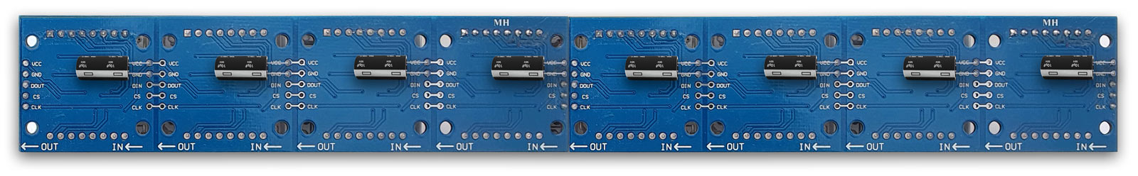
MAX7219 Dot Matrix Module 4 in 1
The display comprises of 2 x MAX7219 Dot Matrix Module. Each module has four 8x8 led matrixes each controlled by a seperate MAX7219 IC.
The modules are daisy chained length ways to make the full 8 matrix display.
Control Panel
The contrl panel houses 6 buttons, 1 off push to make locking and 4 off push to make non locking.
There is a spare position for an extra button if required.
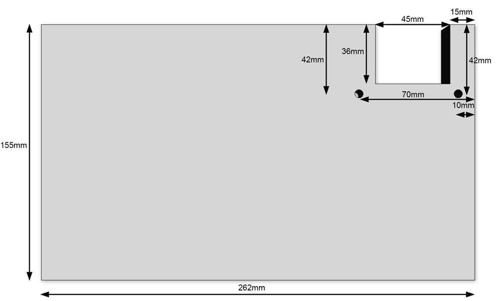
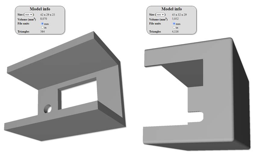
3D Printed Parts
Various 3D printed parts are used and I have included them is case a 3D printer is available.
These parts can be made up from locally sourced materials if a 3D printer is not available.
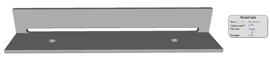
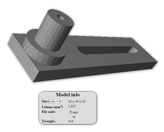
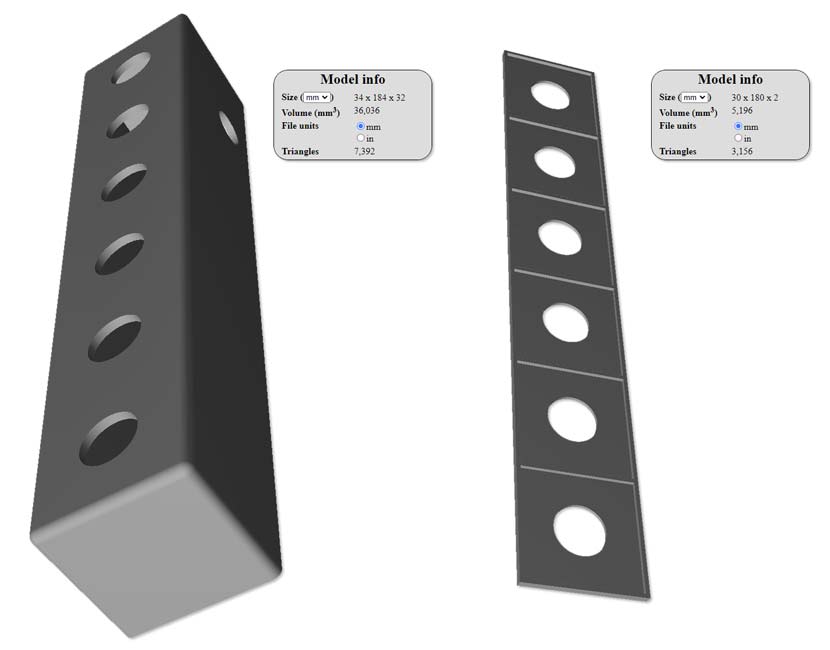
3D Printed Height Bar Brearing support
A full list of 3D parts will be included at the end including a link to the parts on Thingiverse
Construction
Dot Matrix Module Modification
Each of the 8 MAX2719 modules will need to be modified.
The data sheet calls for Supply Bypassing to minimize power-supply ripple due to the peak digit driver currents,
connect a 10µF electrolytic and a 0.1µF ceramic capacitor between V+ and GND as close to the device as possible.
The MAX7219/MAX7221 should be placed in close proximity to the LED display, and connections should be kept as short as possible to minimize the effects of wiring inductance and electromagnetic interference.
Also, both GND pins must be connected to ground.
My modules had a 0.1µF ceramic capacitor between V+ and GND but the 10µF electrolytic capacitor was not fitted.
I fitted these 10µF electrolytic capacitors to the front of every module by removing the dot matrix LED panel then soldering capacitors to the V+ and ground pins.

above and below Missing Bypass Capacitor soldered in place below the LED Matrix

Alternatively the capacitors can be soldered to the back of the modules. This is quicker and easier but increases the depth of the module.
Main Stadiometer Build
The Stadiometer is built from scrap timber left over from other projects.
The main timber is 2200mm x 18 hardwood engineered Oak flooring joined and braced at the rear.
Bracing and slide mount is 45x20m timber with 38x10mm sides.
Plan Views
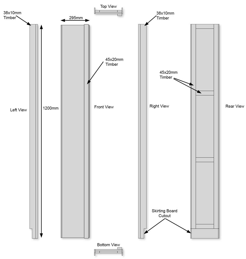
Front and Rear Views

Height Bar
The height bar is cut from an off cut of hardwood flooring and is bolted the the slide rail.

Height bar in position bolted to the sliding clamp. Plastic cover hide the sliding clamp.
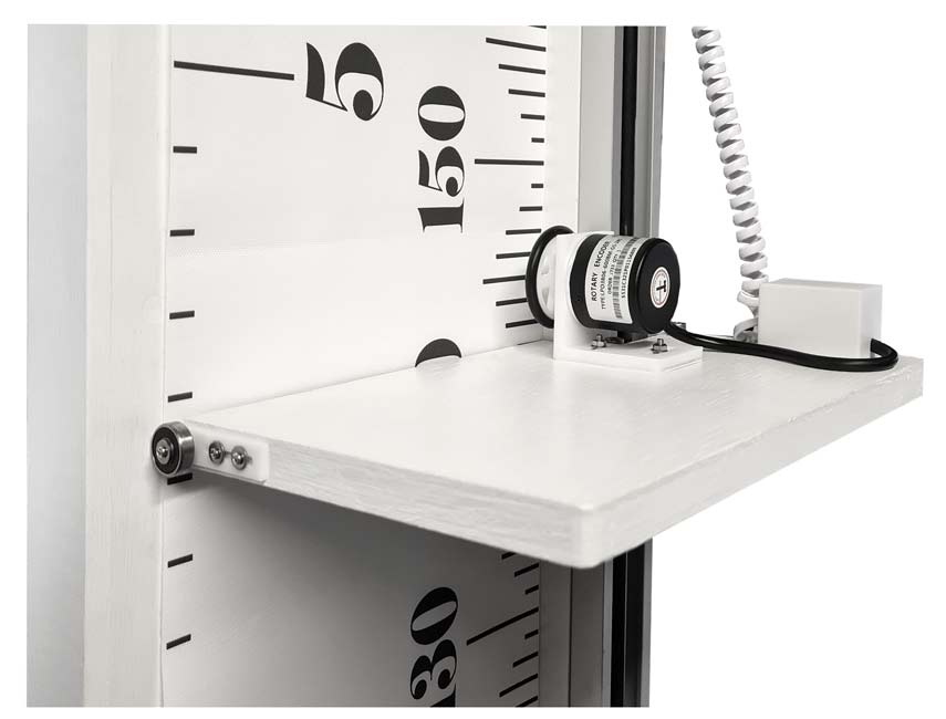
The height bar is supported by a support bearing that runs off the wooden back panel.
Plastic end caps hide the modified end stops top and bottom.
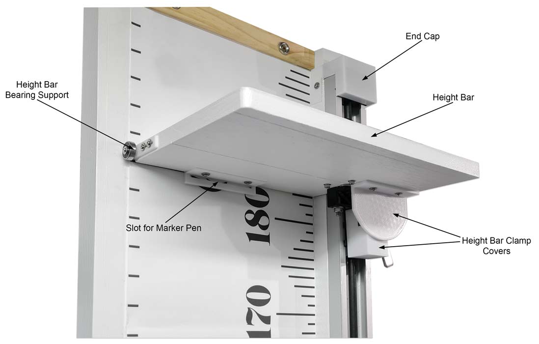
Detail of 3D printed adjustable bearing support
View of Optical Encoder and connection box for the coiled cable
Right side view
Detail of height bar fixing and slide clamp with 3D printed cover removed.

The height bar is bolted to the sliding clamp below.
The lever locks the slide in place when measuring.
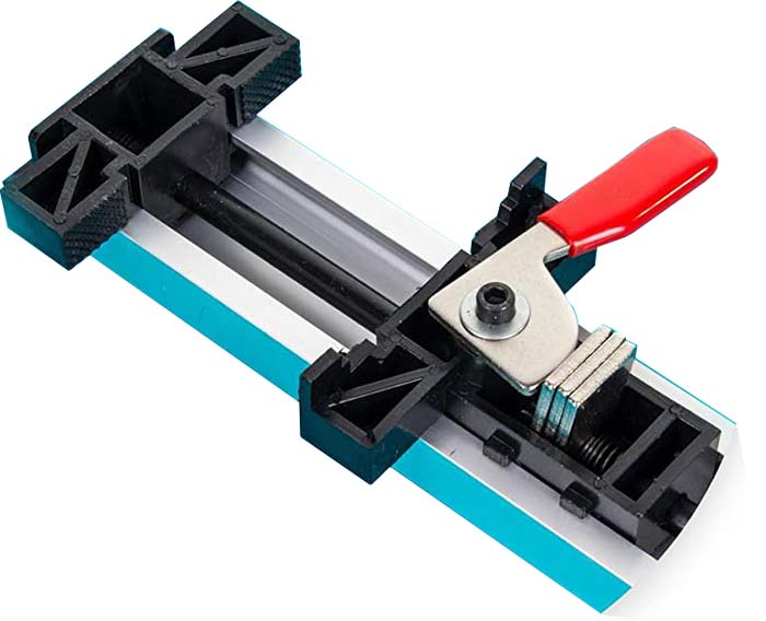
The top and bottom stops of the guide clamp are modified by chopping the plastic stops flush with the alumnium channel.

Control Panel
The control panel is 3D printed from 2 parts the lower box and upper panel for the labels.
The upper box is printed in 2 layers white then black for the square button bounderies.
2 layer printing setup instructions can be viewed here Printing 2 colour layers
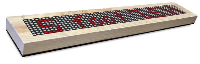
Dot Matrix Display Case
The case for the Matrix display is cut from a solid piece of wood flooring.
A cutout is made the same size of the dot matrix display modules using a jigsaw.
Rear of case wih modules in place. Foam strips hole the LED Matrix modules in place against the perspex fron cover.
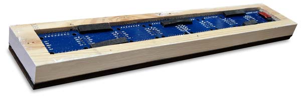
The rear cover plate is made from an off cut of plywood, the rear and sides are painted plack.
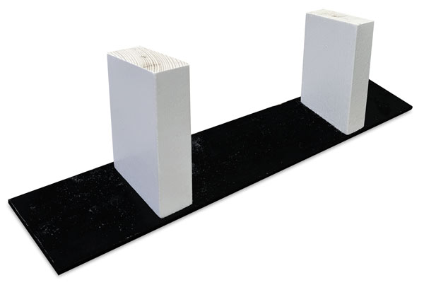
Two wooden legs are fixed to the rear of the cover with screws.
The rear cover is fixed to the back of the case with M2 woodscrews.
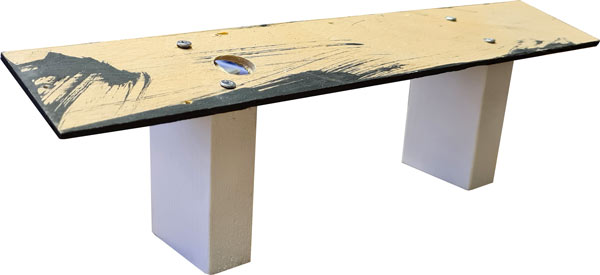
The frnt of the display case is shown below without the neutral density perspex cover in place.
Without the neutral density cover the display lacks contrast and is difficult to see in daylight.
The pic below shows the difference the neutral density Perspex makes with only the red LEDs showing once its in place.
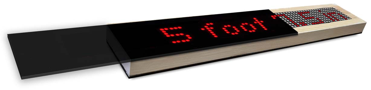
Completed Matrix display in case. The Perspex sheet is fixed in place by 4 M2 screws and washers.
The display in position on the stadiometer. The display case legs are screwed in place through the back of the stadiometer.
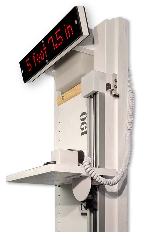
Height Bar Stop & Micro Switch
Mounted on the side of the stadiometer the micro switch is adjusted in it's mount until it just operates before the height bar hits the stop.
The stop prevents the micro switch being damaged if the height bar is forced up too far.
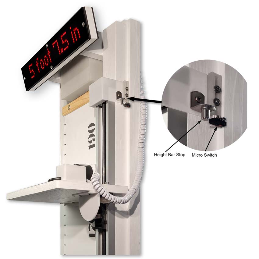
A 3D printed plastic cap is fitted over the top and bottom stops.
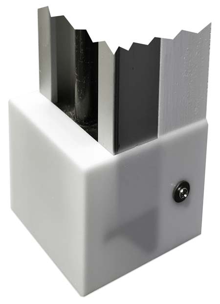
The cutaway image below shows the lower end stop 3D printed cover in place.
The plastic cap is fixed to the timber batton beow the guide rail.
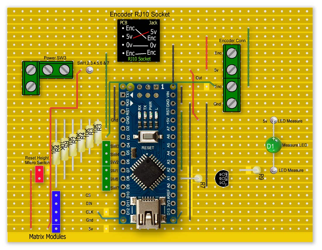
Schematic
Measure remote is wired away from the stadiometer and allows measurement of small children away from the stadiometer without affecting the measurement

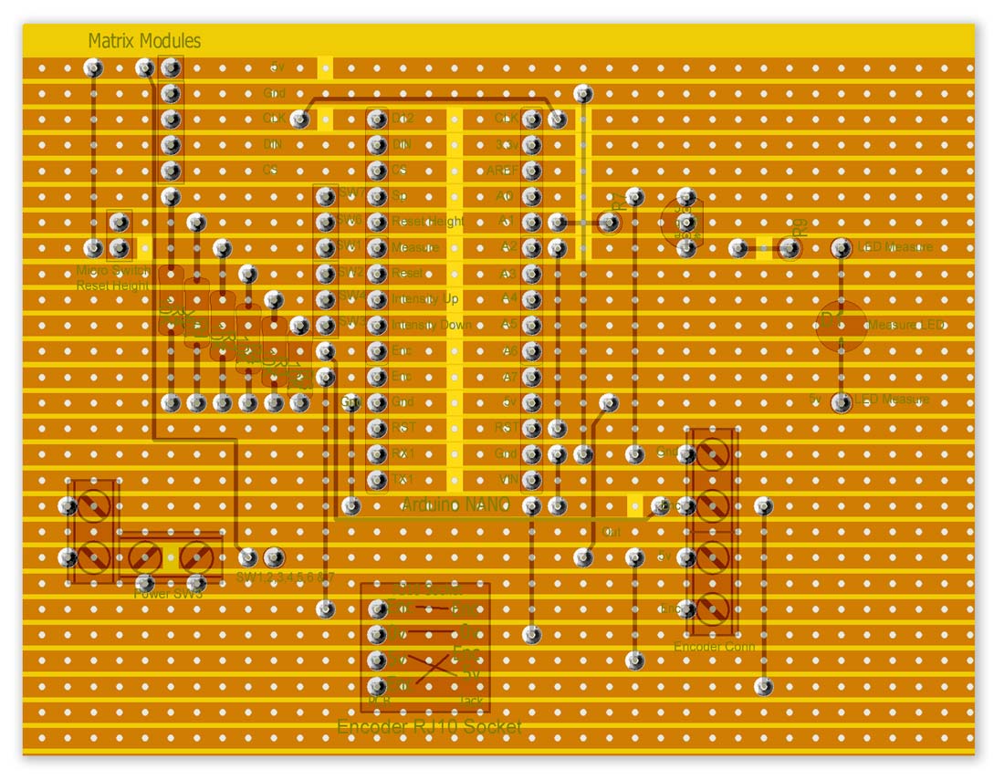
Veroboard Layout

Veroboard with NANO in place
Vero Board Rear flipped up
A spacer for the Vero Board is 3D printed to hold it away rom the case.
![]()
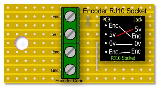
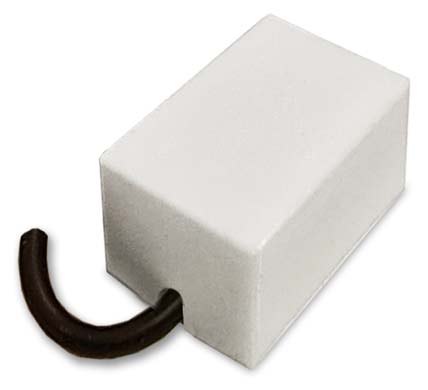
RJ10 Socket Veroboard
This board has the Optical Encoder connected in the screw terminals and the RJ10 coiled cable plugged into the socket.
The other end of the coiled cable pluds into the RJ10 socket on the main board above.
3d printed Vero Board mount left and cover right
Vero Board mount with top cover in place
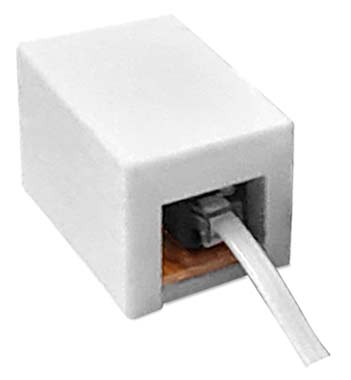
RJ10 PCB Mount Sockets

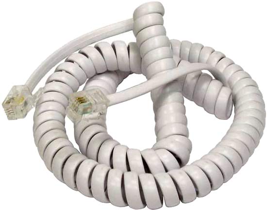
2M Coiled Cable with RJ10 Plugs
3D Printer Files
Contains all the files to print in Cura as well as FreeCad files
Code
Arduino Files