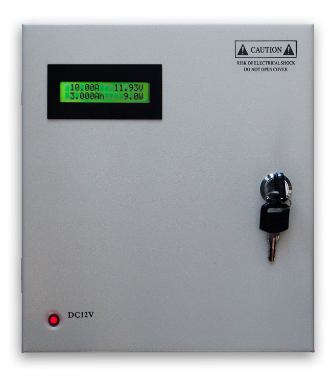
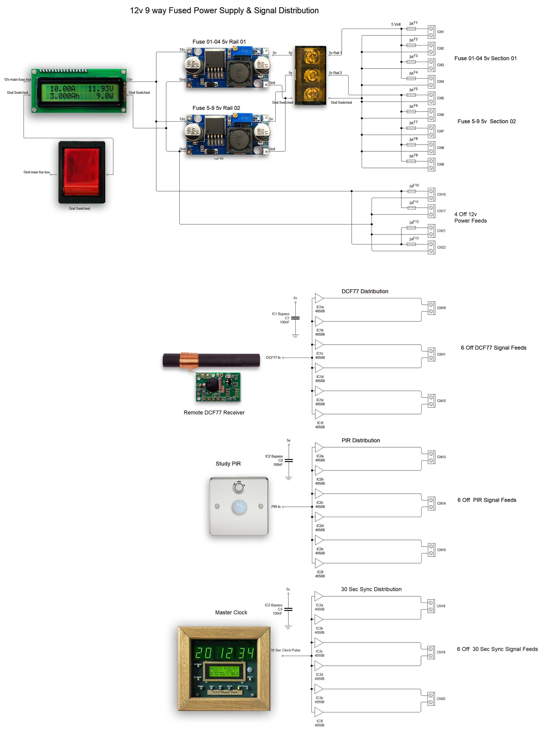
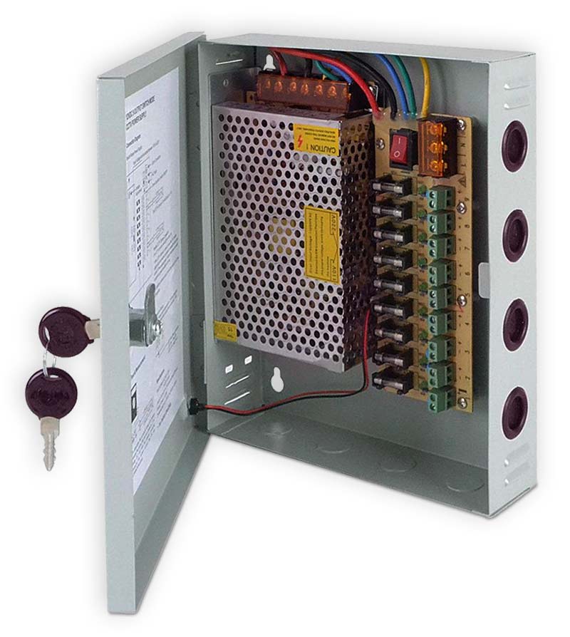
PSU & PULSE DISTRIBUTION BOX
5v & 12v Power & Pulse Distribution Box.
The box uses a modified 240v CCTV camera power supply that has been modified to be fed from my main
battery backed up power supply unit. The box takes a single 12v unregulated feed from my main power supply box and supplies the following outputs.
9 x 5v fused regulated and 4 x 12v fused unregulated outputs.
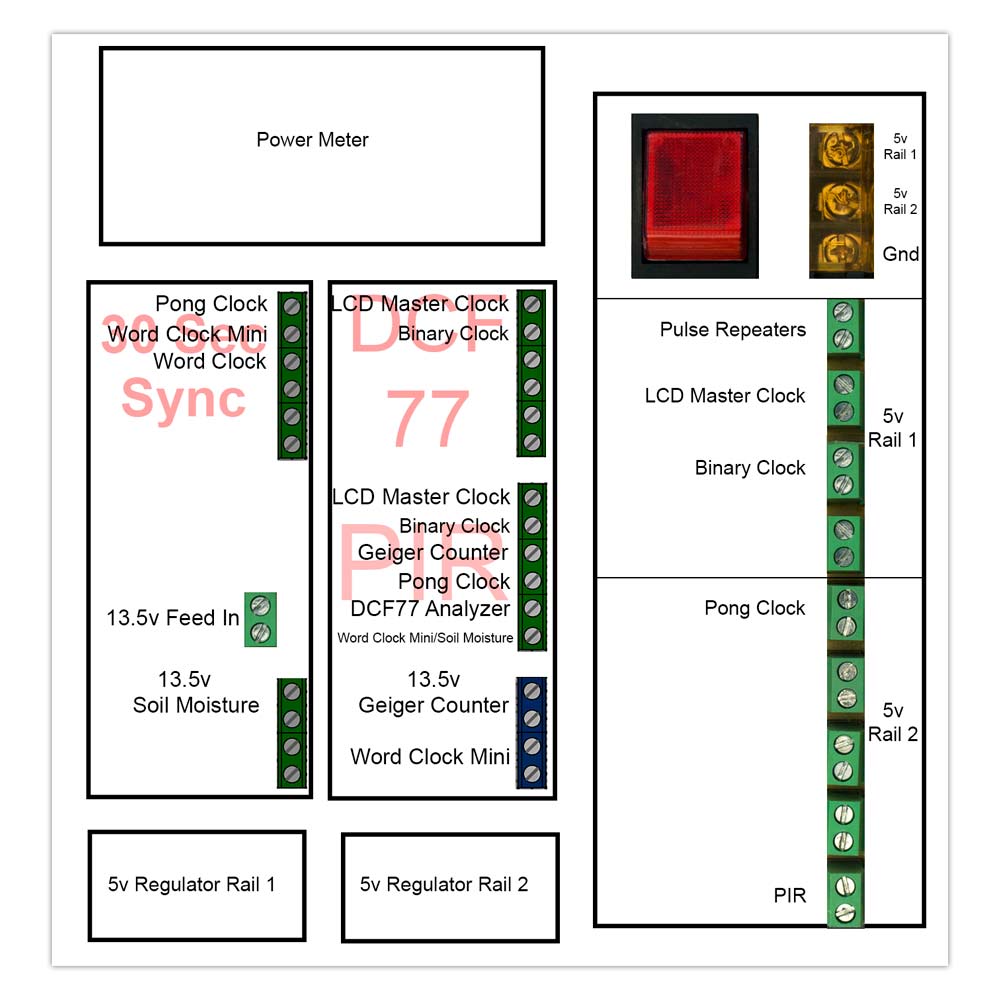
6 x 30 second master Clock pulsed outputs for clock synchronization.
6 x PIR controlled outputs to blank clock displays when unattended.
6 x DCF77 Atomic Clock pulses to drive DCF77 clock receivers from a common DCF77 Aerial and receiver.
The box uses an old power meter to monitor the power from the main PSU.
Wiring and Module Interconnections
The main battery backed up PSU on the left has a fused feed to the Power & Pulse Distribution Box on the right.
PIR,DCF77 and 30 second sync pulses are fed into the Power and Pulse Distribution box before being connected to the devices as required.

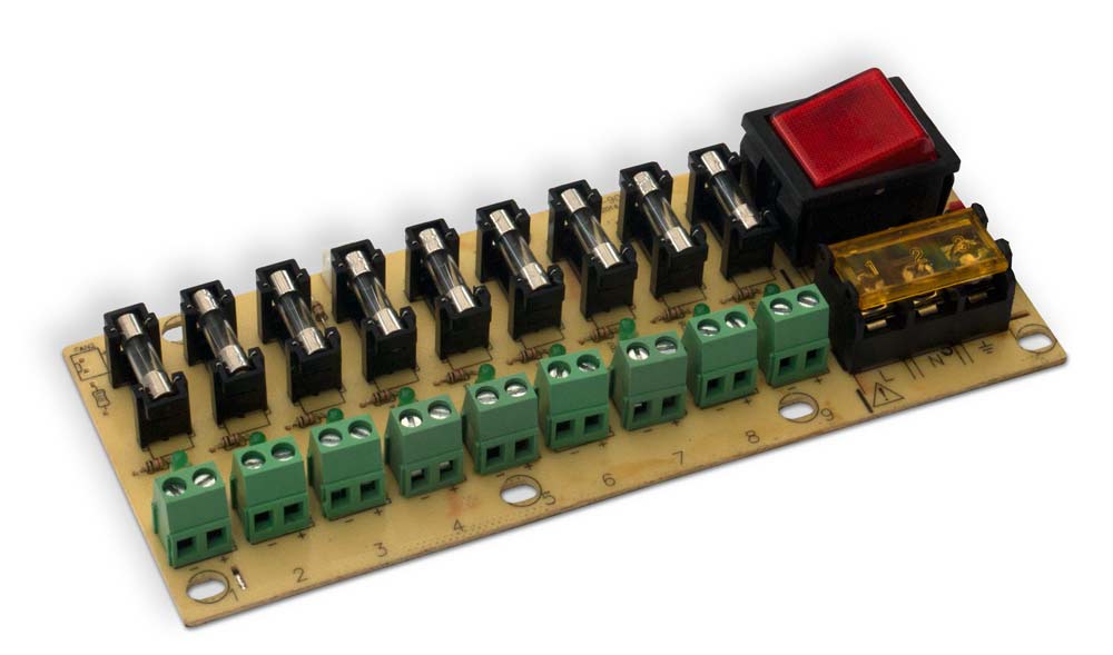
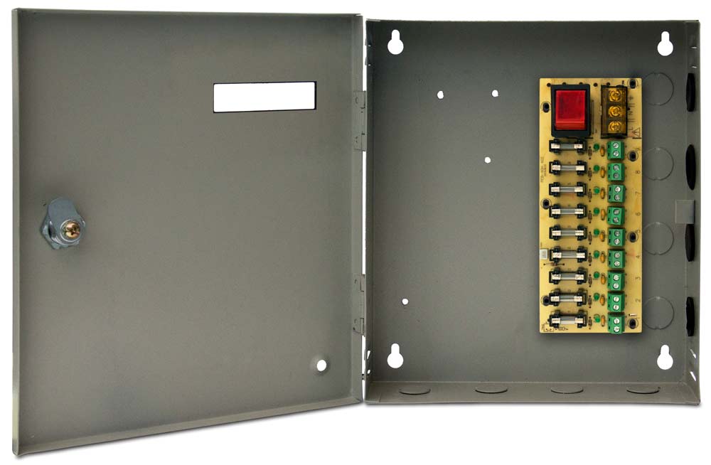
9 way 5v regulated Fused output board
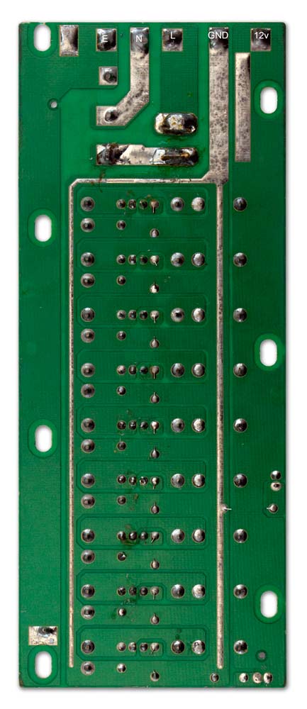
Board showing original 240v and 12v connections before modification.

Modified Board showing the twin 5v rails

PCB Modification
Left is the original PCB with the modified PCB on the right.
There are two track cuts to carry out. This splits the +5v rail into two so each rail can be fed from an individual 5 v regulator.
The separated 5v rails are then wired to the inputs from the regulators.
The ground is common and is switched. The load is monitored on a Volt, Ammeter and Watt Meter.

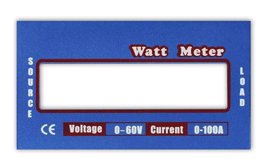
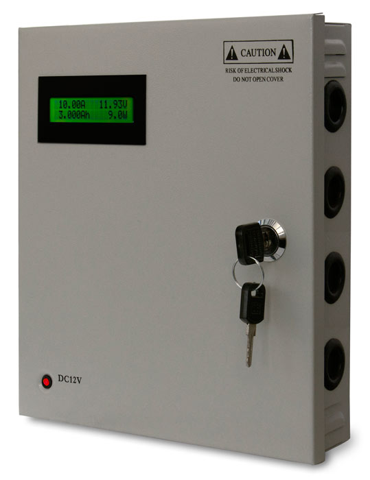
LCD Meter Modification
An old power meter is modified to show power from the main PSU.
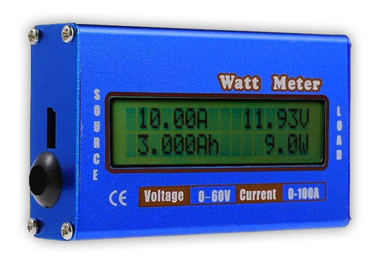
Specification:
Voltage : (0)V-4V-60V 0.01V
(Resolution).
Current : 0-100 A peak 0.01A
(Resolution).
Power : 0-6554 W 0.1W
(Resolution).
Charge :
0-65 Ah 0.001Ah (Resolution).
Energy : 0-6554 wh 0.1 Wh (Resolution).
Measurement Update period : 400mS.
Signal Sampling Rate : sample/s.
Data Queue Sequence time : 2 seconds.
In Circuit Resistance : 0.001 Ohms.
Operation Current : 7 mA.
Auxiliary Power Voltage : 4.0V ~ 60V
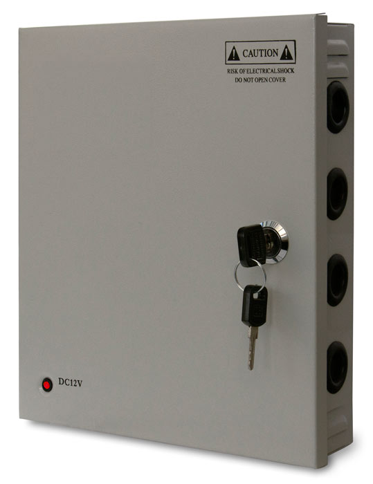
Power meter in it's original case

Remove the LCD display and control module.

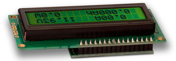
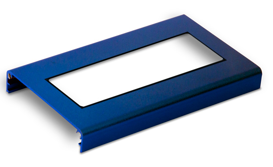
The top half of the case is used as a display bezel on the front of the new PSU.
Mark 2 lines on the top of the case.
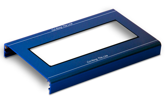
Cut down the 2 lines to leave a flat display bezel.
The bezel is then painted black

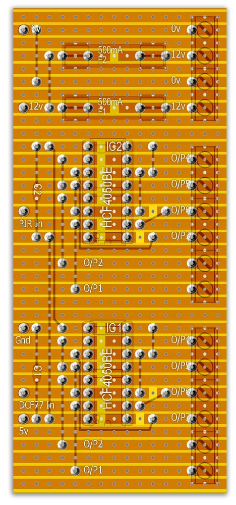
Vero Boards
2 Vero Boards are required 1 for the 30 sec sync repeater and 1 for the DCF77 repeater& PIR repeater.
Both Vero Board each have 2 x 12v unregulated outputs for clocks with built in voltage regulators.
The repeaters are HCF4050BE Hex non-inverting Buffer/Converters. All they do is take 1 I/P and re-produce the I/P on 6 outputs.
This way I only need 1 off DCF77 receiver, 1 off 30 sec Master Clock Pulse and 1 off PIR detector to drive 6 clocks/devices.
In practice each output can drive at least 2 devices each.
Vero Board 1 Layout Front
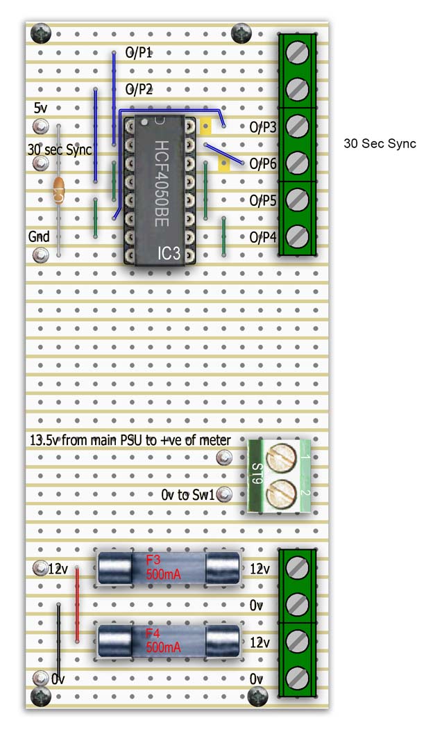
Vero Board 1 Layout Rear
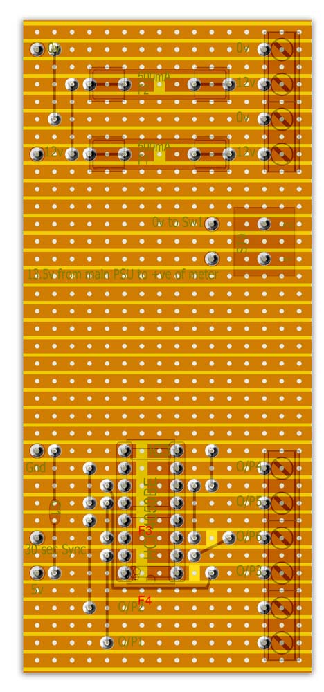
Vero Board 2 Layout Front

Vero Board Layout Rear
Schematic
CASE MODIFICATION
The case is stripped out and the original PSU is put aside as it is no longer required.

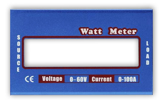
A slot is cutout of the lid to take the display. A bezel is made out of the old aluminum box and painted black.
Hole are drilled for mounting the LCD and Vero Board timber mounts.
The PCB is modified and then re-inserted in the case.
The Meter display is mounted on a block of wood spaced at the correct height to touch the lid of the case.
A piece of plywood is cut to size and painted black and then fixed to the case with screws.
The vero Boards and PSU Regulators are fixed to the plywood backing board with screws.


![]()
Completed case ready for wiring.

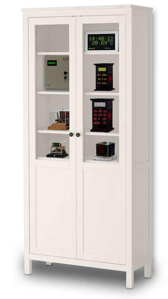
The distribution box powering and connecting a number of devices in my workshop display cabinet