
Section Top Changes Controls Setup Animation Sync 3D Printed Parts Electronic Modules Schematic Vero Board OHP Sheet Layout Code
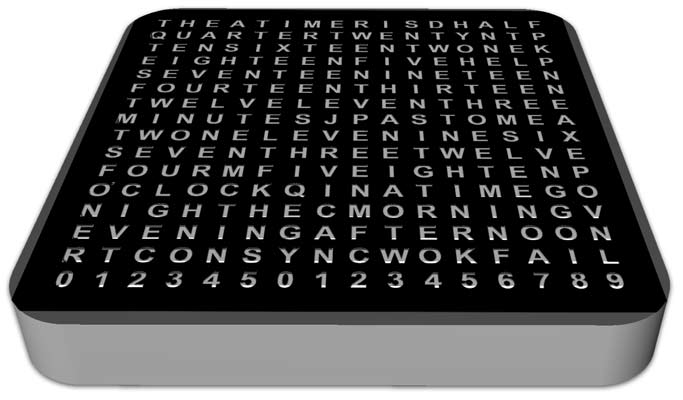
Using a WS2812B 16x16 RGB LED Matrix & WEMOS D1 Mini
Detail
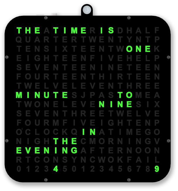
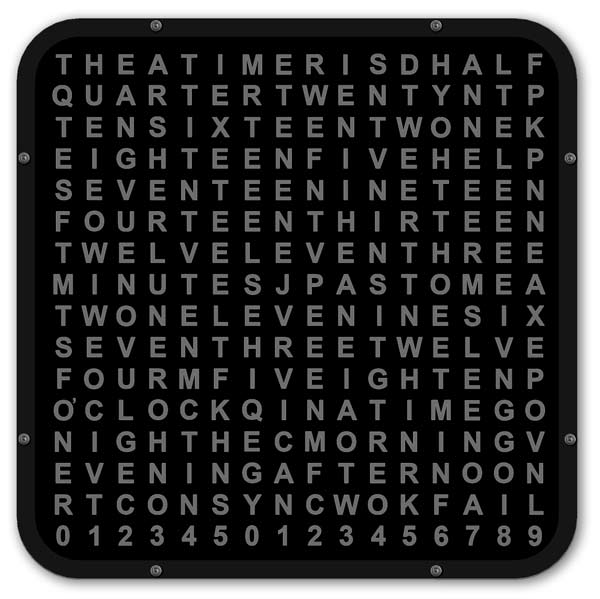
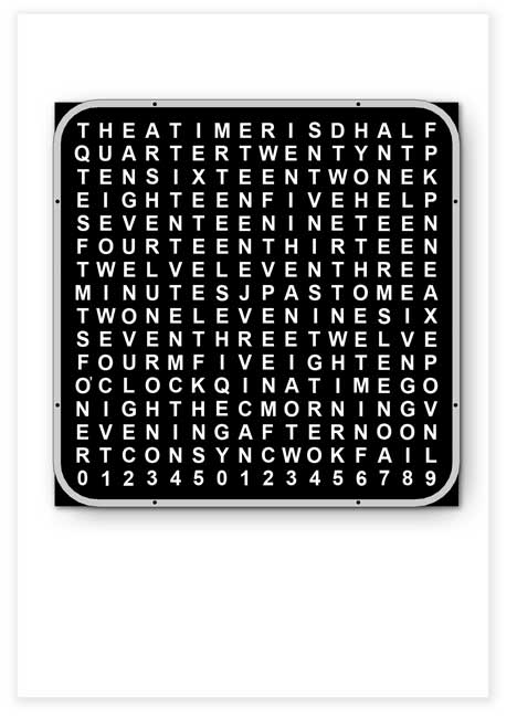
This is a 256 Digit Word Clock using a Wemos D1 Mini Module & a 16x16 WS2812B RGB LED Flexible Digital Light Panel.
The clock is initially setup from a web interface including NTP server address for time setting.
Once set from an NTP server the clock will run off it's internal RTC.
The RTC is synchronised hourly if you have a local NTP server or daily if an internet NTP server is used.
Credit
This clock is based on the "Word Clock on an LED Matrix" by g3HjMJ6huqVgt9b. See it on Thingiverse
The display with linear seconds was based on my original word clock.
The clock measures 180mm x180mm plus 15mm on the top for the PIR housing.
Changes to the original clock
I have done away with the 3D printed clock digits and instead print the digits onto overhead projector clear film.

These sheets are very cheap and the display can be printed in seconds making it very easy to make changes to the display.

Using Meashmixer I have sliced away the digits from the original 3D stl file leaving just the LED matrix and thin LED diffuser layer above the matrix.
Below I have sliced off the top dark layer right leaving the clock body with thin diffused layer on top.
Printing the main clock body.
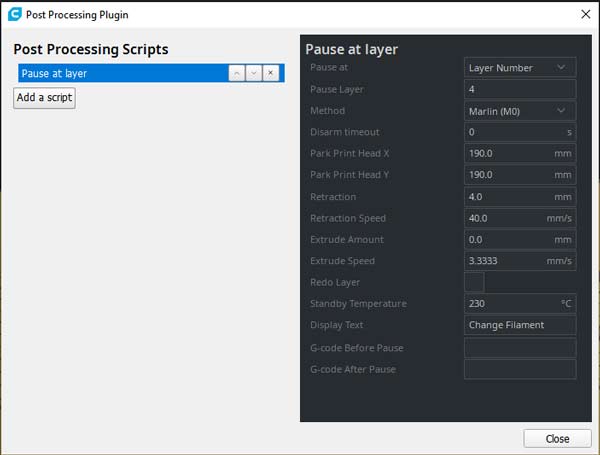
The main clock body is printed in 2 separate layers/colours.
The first 4 layers are printed in clear then the printer is paused, the filament changed to black then all the other layers are printed in black.
I have used a post processing script in CURA to do this.
Full details of how do do this can be found here Pause at layer
This is the Post Processing Script Screen settings I used when printing the clock body.
OHP film laid over 3D printed matrix.
The film is held in place by a 3D printed dial surround screwed to the matrix.
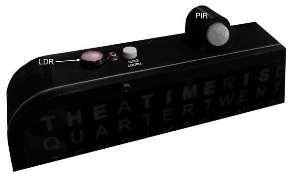
I have kept the clock control button but mounted it on the top left of the clock case.
The rear of the case has been modified and now has a larger rear box to hold my Vero board.
I have added a RTC so once synchronised to an NTP time server the clock will keep good time even if NTP time sync fails in the future
On boot up synchronisation info is shown on the display
A PIR is fitted to shutdown the display if no one is in the room
An LDR keeps the display at optimum brightness
The display colour is set on the web server interface but can be changed while the clock is running
In case like me you run your own NTP server I have added to the web interface an option of using the local NTP time
The boot has been changed so if NTP login fails the RTC time is used instead rather than restarting the clock in the web interface
The RTC is synchronised hourly for local NTP servers and and daily NTP sync for internet NTP servers
Animations and timings added for custom Birthday and Christmas day messages on the hour
Event date added in web interface so a message can be displayed on birthdays or anniversaries if animations are enabled
A 2 second hold of the clock button resets the clock and forces a re-sync
Holding the clock button on power up forces the clock into the web interface
I have also added a Winter/Summertime toggle by double clicking the Clock Control Button
Clock Control Button
The clock has a single multifunction button to setup and control the functions.
Double click- toggles winter/summertime.
Single click- cycle display colour.
Colour cycles in this order Blue, Green, Red, Purple, Yellow, Orange, Teal & White.
Initially the colour will start at the colour chosen in the web setting interface.
Press and hold for 2 seconds to reset the clock and re-synchronise.
Press and hold for 5 seconds resets the web settings and launches web interface.
Press and hold on power up resets web settings and launches web interface.
Setup
On the original clock on power up if the NTP login fails the Web Server is automatically loaded and the clock will not start.
On my version with a RTC if the clock is unable to login into the web server the RTC time is loaded up.
If the RTC has never been set it will start from midnight and not show the correct time.
To setup the RTC and NTP server the clock button is held down on boot.
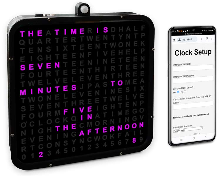
This loads the web interface under a WIFI hotspot called "Clock Setup........ " with the IP address shown.
In normal clock mode holding down the clock button for 5 seconds restarts the clock clears the clock settings and loads the web server again.
Loading the web interface.
On a WIFI device access your WIFI settings.

On this example using an Android device drag down the menu from the top bar.
Press and hold the WIFI icon on the left.
Thhis will bring up the WIFI connections screen.
The phone is connected to "BTHub6"
As the clock is in the web interface mode it has created a it's own network " Clock Setings 192.168.4.1"
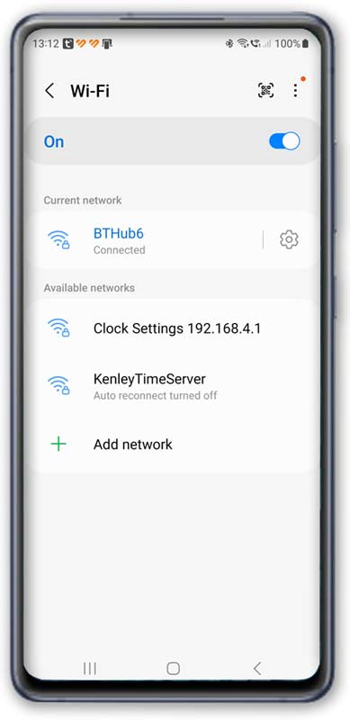
Click on this network and your phone will connect without internet.
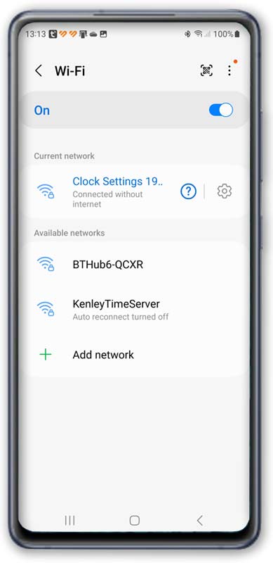
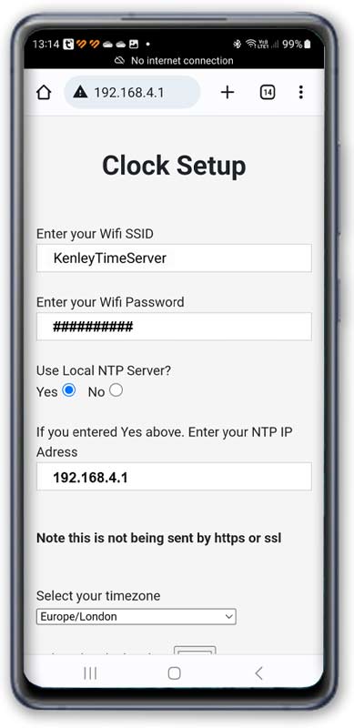
Go to your internet browser and enter the Clock setting server address "192.168.4.1"
Your browswer should show the clock setting interface.
I have my own NTP server ( see http://www.brettoliver.org.uk/GPS_Time_Server/GPS_Time_Server.htm ) and have added a "Use Local NTP Server" option to the menu.
If you don't have your own NP sever un-tick the "Use Lacal NTP Server?" box and enter your router SSID and password.
If you have your own NTP server enter the WIFI SSID and password of the NTP server.
Make sure the "Use Lacal NTP Server?" box is ticked and enter the IP address of your NTP Server.
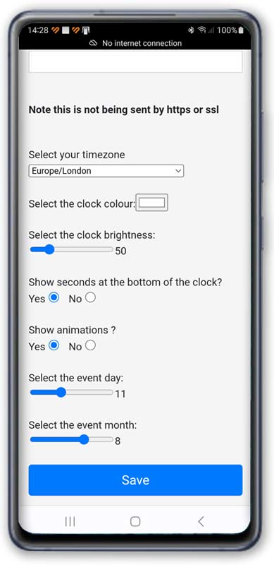
Select your timezone in the drop down menu (I have added Europe/London to the top of the list).
Scroll down the page and select the startup clock colour.
Note This can be changed when the clock is running by clicking the clock button.
The clock brightness setting can be ignored as it is set by the LDR.
Select if you want to sow the seconds at the bottom of the clock.
Show animation can be set to on or off. Animations are displayed on the hour.
Set the "Event Day" slider for the birthday or aniversay day.
Set the "Event Month" slider for the birthday or aniversay month.
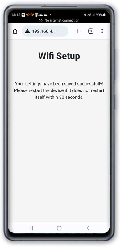
Click save and the selected options are then loaded into the clock.
You should get a message that settings have been saved.
The web server now disconnects and your phone should re-connect to your router.
The clock will then attempt to restart and get the time from the NTP server.
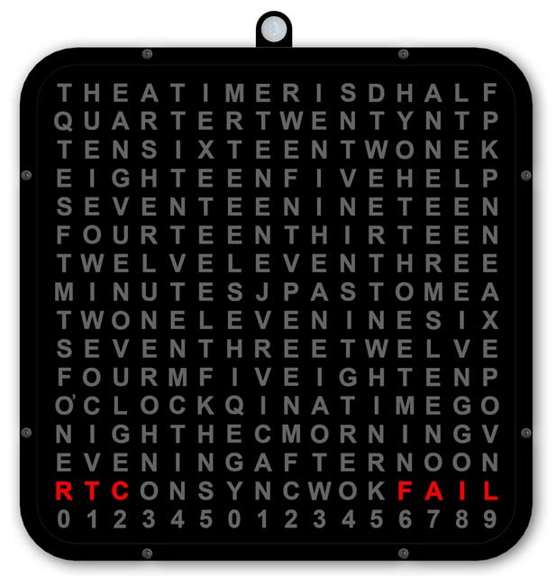
On power up the clock will try and communicate with the RTC.
If it is unable to do this it will stop and show "RTC FAIL" on the display.
Sort out the RTC issue to continue.
If the RTC is OK the clock should show "NTP TIME SYNC" and the number of attempts will be shown on the display.
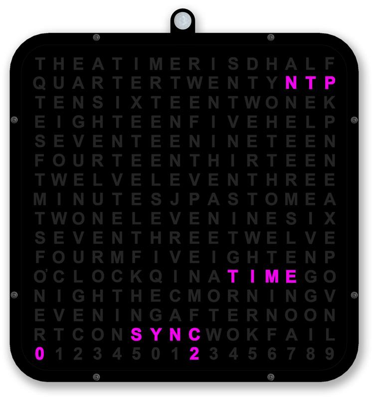
If after the attempts reach 30 and "NTP TIME SYNC FAIL" is displayed the clock will restart using the non synchronised time from the RTC.
You will need to check the settings again hold down the clock button for 5 seconds to restart the web interface.
If the display shows "NTP TIME SYNC OK" the RTC clock will be synchronised to the NTP server.
If you have animation set to on then the animation will be displayed followed by the time.
If animation is off then the time will be displayed.
Animation settings
There are a number of animations included in the original code. Just search for "textanim".
Textanim1 displays the time on a rainbow matrix.
I use textanim2, 3 and 3a which display a scrolling name or word on a rainbow matrix. The is called on the hour depending on the birthday set or if it's Christmas day.
textanim2 displays the message set in code and shows on the hour except birthdays and Christmas day.
Changing the scrolling text
The code below shows the start of textanim2. The original work tick tock has been commented out and replaced by a name "Lyra Austin".
You have to change it in 2 lines.
Just change the name as required to whatever you want.
|
void textanim2() { int x = matrix.width(); // char yourText[64] = "Tick Tock"; char yourText[64] = "Lyra Austin"; int pixelPerChar = 6; int maxDisplacement; maxDisplacement = strlen(yourText) * pixelPerChar + matrix.width(); for (int pass = 0; pass < 150; pass++) { int i = 0; i++; //matrix.fillScreen(0); for (int y = 0; y < 16; y++) for (int x = 0; x < 16; x++) if (y & 1) matrix.setPixelColor(15 - x + y * 16, matrix.gamma32(matrix.ColorHSV((x + y) * 256 * 8 + i * 128 * 2))); else matrix.setPixelColor(x + y * 16, matrix.gamma32(matrix.ColorHSV((x + y) * 256 * 8 + i * 128 * 2))); matrix.setTextColor(matrix.Color(0, 0, 0)); // matrix.setCursor(-((millis() / 30) & 127) + 20, 4); matrix.setCursor(-((millis() / 40) & 127) + 20, 4); //Brett matrix.print(F("Lyra Austin")); //matrix.print(F("Tick Tock")); //Brett matrix.setBrightness(brightness); //End brett matrix.show(); delay(40); } |
|
textanim3 displays the birthday/anniversary or event message set in code
Changing the scrolling text
The code below shows the start of textanim3. Just replace the message "Happy Birthday Lyra" highlighted in yellow with your own message.
You have to change it in 2 lines.
The day this message is displayed is set in the web interface.
| void textanim3() { int x = matrix.width(); char yourText[64] = "Happy Birthday Lyra"; int pixelPerChar = 6; int maxDisplacement; maxDisplacement = strlen(yourText) * pixelPerChar + matrix.width(); for (int pass = 0; pass < 150; pass++) { // brett cheged pass from 80 to 150 int i = 0; i++; //matrix.fillScreen(0); for (int y = 0; y < 16; y++) { for (int x = 0; x < 16; x++) { if (y & 1) { matrix.setPixelColor(15 - x + y * 16, matrix.gamma32(matrix.ColorHSV((x + y) * 256 * 8 + i * 128 * 2))); } else { matrix.setPixelColor(x + y * 16, matrix.gamma32(matrix.ColorHSV((x + y) * 256 * 8 + i * 128 * 2))); } } } matrix.setTextColor(matrix.Color(0, 0, 0)); //matrix.setCursor(-((millis() / 30) & 127) + 20, 4); matrix.setCursor(x, 4); matrix.print(F("Happy Birthday Lyra")); matrix.setBrightness(brightness); if (--x < -maxDisplacement) { x = matrix.width(); } matrix.show(); delay(40); } } |
textanim3a displays the Christmas message set in the code
Changing the scrolling text
The code below shows the start of textanim3a. Just replace the message "Merry Christmas Lyra" highlighted in yellow with your own message.
You have to change it in 2 lines.
The day this message is displayed is set for Christmas day in code.
If you want to change the date search for "Display Christmas message".
| void textanim3a() { int x = matrix.width(); char yourText[64] = "Merry Christmas Lyra"; int pixelPerChar = 6; int maxDisplacement; maxDisplacement = strlen(yourText) * pixelPerChar + matrix.width(); for (int pass = 0; pass < 150; pass++) { // brett cheged pass from 80 to 150 int i = 0; i++; //matrix.fillScreen(0); for (int y = 0; y < 16; y++) { for (int x = 0; x < 16; x++) { if (y & 1) { matrix.setPixelColor(15 - x + y * 16, matrix.gamma32(matrix.ColorHSV((x + y) * 256 * 8 + i * 128 * 2))); } else { matrix.setPixelColor(x + y * 16, matrix.gamma32(matrix.ColorHSV((x + y) * 256 * 8 + i * 128 * 2))); } } } matrix.setTextColor(matrix.Color(0, 0, 0)); //matrix.setCursor(-((millis() / 30) & 127) + 20, 4); matrix.setCursor(x, 4); matrix.print(F("Merry Christmas Lyra")); matrix.setBrightness(brightness); if (--x < -maxDisplacement) { x = matrix.width(); } matrix.show(); delay(40); } } |
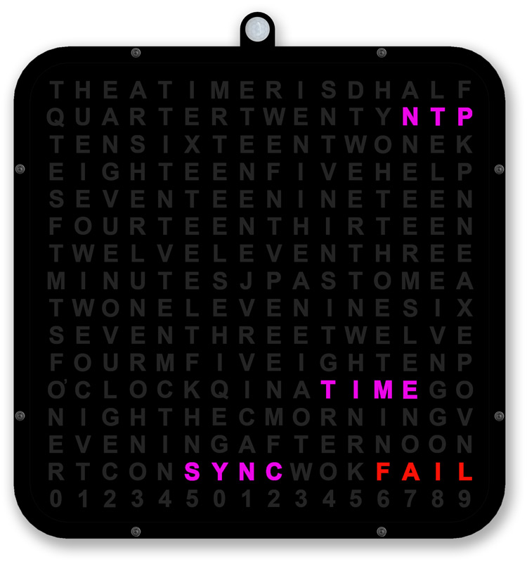
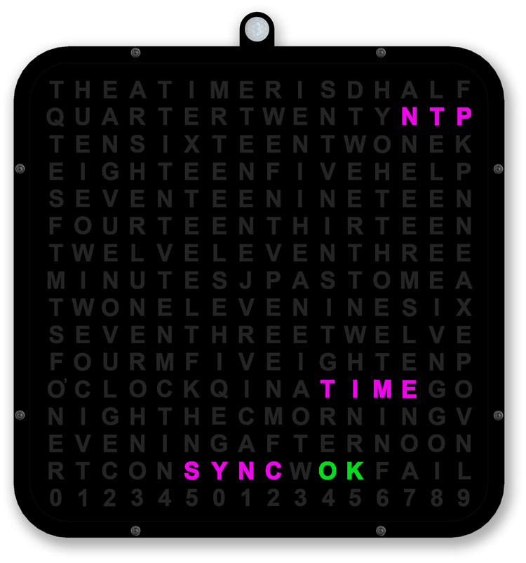
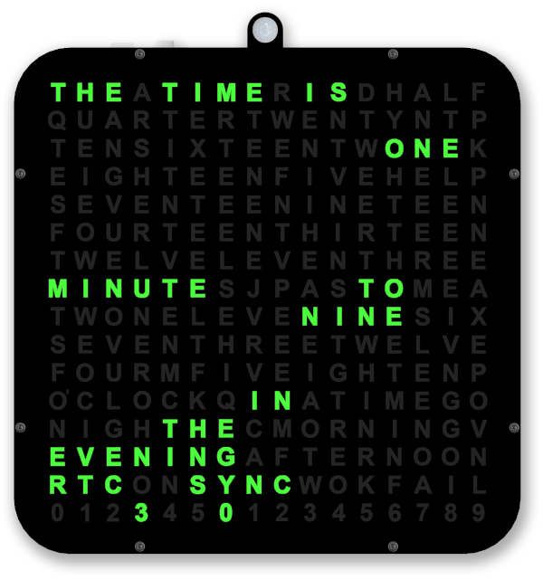
Clock Synchronisation
The RTC is synchronised hourly 1 minute to the hour if a local NPT server is used or daily 01:00 hrs if an internet NTP server is used.
The animation below shows a local NTP sever RTC Sync at 1 minute to the hour.
At 59 mins and 1 seconds RTC sync is shown on the display.
At 59 mins and 5 seconds the seconds will stop updating as the RTC is synchronised to local NTP time.
The clock will attempt to Sync for upto 30 times.
Once sync is obtained or fails the seconds restart synchronised if Sync was OK or where they left off if sync failed.
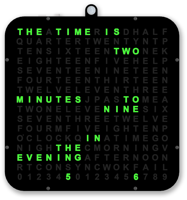
Once sync has been attempted the result is shown on the display after 34 seconds and the result will be cleared after 59 seconds.
If synchronisation was successful "RTC SYNC OK" is displayed.

If synchronisation was un-successful "RTC SYNC FAIL" is displayed.
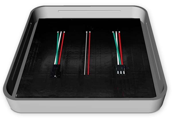
3D Printed Parts
Clock Body
From the original project I have re-used only the Clock_body.
Using Meshmixer I have changed the clock body by slicing off the digits leaving the solid layer and LED Matrix below.
The original clock body is on the left and after editing in Meshmixer I was left with a flat top box with the LED matix below the top layer.
The LED diffuser layer is created by printing in 2 layers with clear PLA for 4 layers then all the other layers in black PLA.
This is the rear view of the new part showing the LED matrix with clear LED diffuser layer below.
The display printed on clear overhead projector sheet (OHP) lays on top of the diffuser layer.
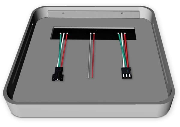
Front Bezal
A front bezal is fixed over the clock body and holds the over head projector film in place.
A 1mm thick sheet of perspex holds the OHP sheet flat and protects it.
The bezal is fixed to the clock body with M2 bolts.
Rear view of front bezal showing recess for 1mm perspex sheet and OHP display sheet.

Construction layers
Starting with the clock body.

Lay the OHP display sheet on the clock body
Lay the 1mm Perspex sheet on top of the OHP sheet
The bezal is placed on top ensuring the Perspex and OHP sheets sit in the recess.

Finally the allen bolts are screwed in to hold the completed display in place.
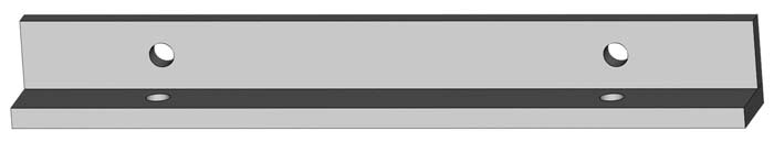
LED Matrix Support
The support fits in the rear of the case on top of the LED matrix to hold it in place.
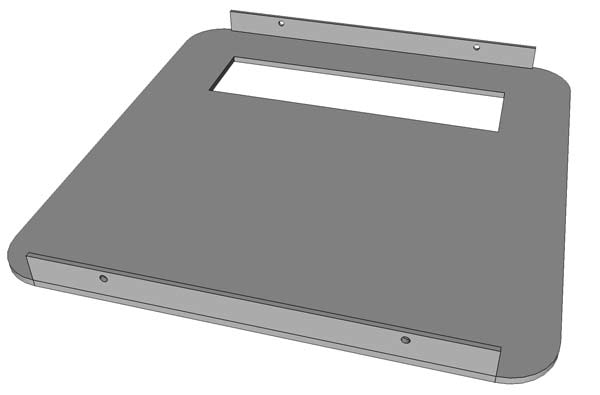
Rear view of the main clock body.
LED Matrix in place in the rear of the main clock body.
The LED Matrix Support fits on top of the LED Matrix with the LED matrix connections fed through the slot.
Vero Board Support Spacer
The spacer fits under the Vero Board and is glued to the Matrix Support
![]()
Vero Board spacer shown in position on the LED matrix support.
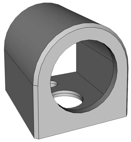
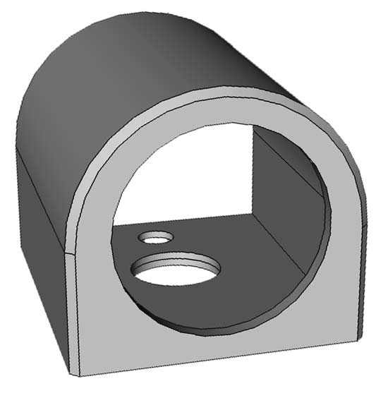
PIR Sensor Mount
The PIR sensor is mounted in this housing.
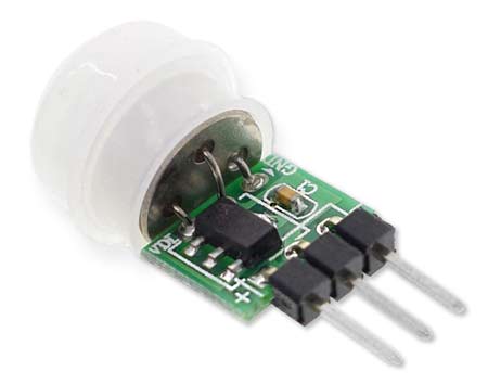
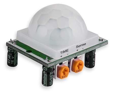
SR501 PIR module showing SR505 PIR sensor under the diffuser cap.
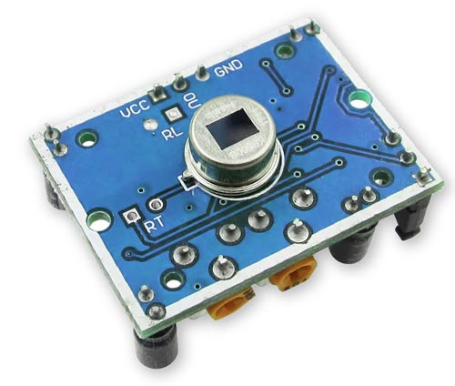
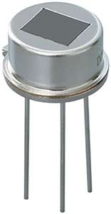
Due to limited space the SR501 is de-soldered from it's PCB.
SR501 PIR Sensor
3D printed PIR spacer
![]()
The SR501 PCB is fixed to the LED Matrix support near the SR501 and 3 wires are taken from the PCP to the SR501.
The small hole in the Sensor mount is for a M2 fixing bolt and the larger hole for the 3 wires to the sensor.
The main clock body and LED Matrix support will need to be drilled for the bolt and wires.
The PIR sensor can be mounted on the top or bottom of the clock so just drill the holes as required.

If you are using the AM312 PIR a larger PIR mount is required.
The mount is large enough to hold the sensor and PCB.
The PIR spacer is not required if you use this PIR module.
Rear Panel construction layers
Rear view with wall hanger box in place over the Vero Board.
Wall hanger and fixing brackets removed showing the Vero Board fixed to the LED Matrix board.
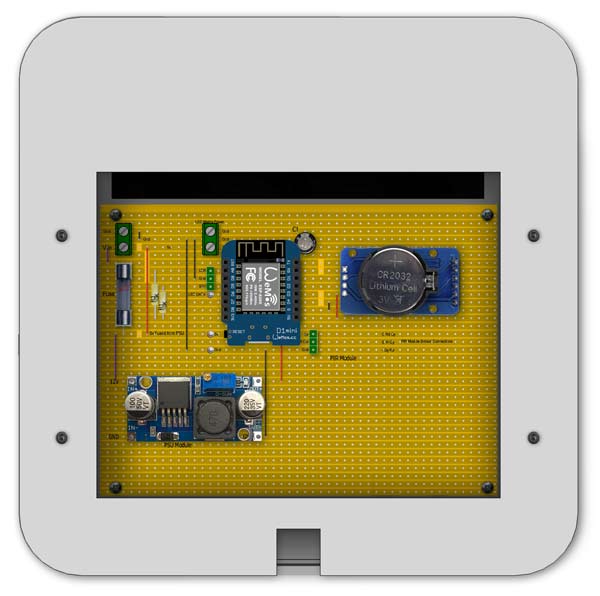
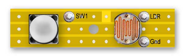
Vero Board in place with rear panel removed showing PIR PCB & Switch/LDR Vero board location.
If your PIR is an AM312 then the PCB fits in the housing
The PCB is held in place on the PIR spacer by 2 x M2 self tapers.
Vero Board in place with rear panel removed
Vero Board spacer in place below Vero Board.
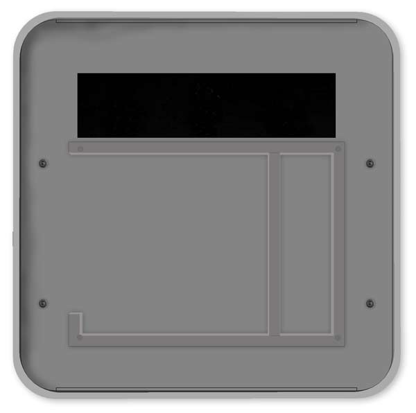
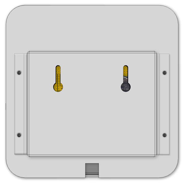
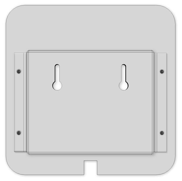
Rear Panel
I have designed a new rear panel that will give space for the extra electronic modules.
The panel has a cable cutout and a cutout for a back box. The back box gives the extra room for the electronic modules.
Rear panel inside view.

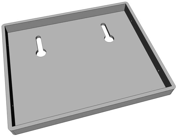
Rear Panel Back Box
The back box has a pair of hols so it can be mounted to a wall.
The back box is fixed to the rear panel by a pair of brackets 2 M3 x self tappers and 2 x M3 bolts/nuts.
The self tappers fix the brackets to the back box and the bolts fix the other side of the brackets to the rear panel.
Rear panel to back box bracket 2 off
Rear view of completed rear panel showing back box and brackets.
LDR Diffuser
Printed in clear PLA and glued over the LDR
Switch & LDR Vero Board spacer
Bolted to the Vero Board and provides spacing for the switch cover protrusion from the clock body.
![]()
Spacer in place.
![]()
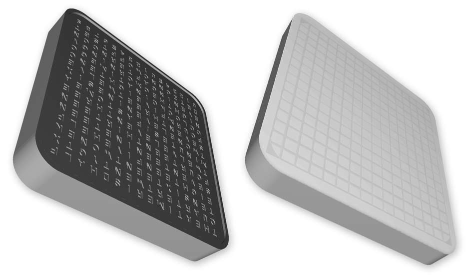
OHP Film Cutting Template
The template is used as a guide for cutting the OHP film to size.

3D Printed Parts Download

Electronic Modules
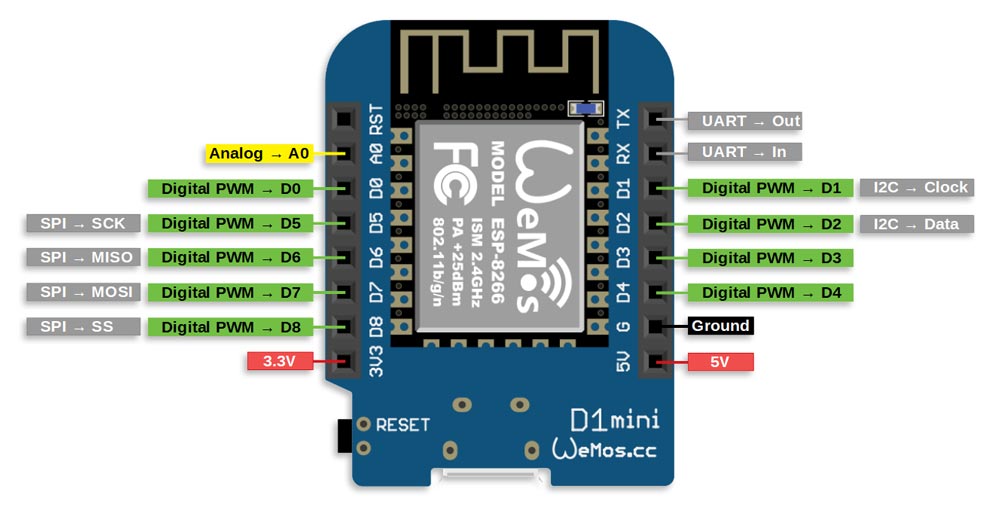
WEMOS D1 MINI
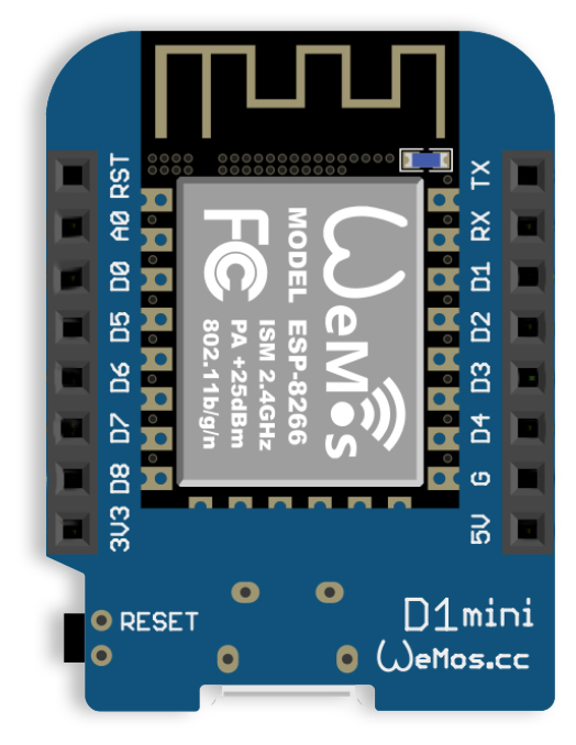
The WeMos D1 min PRO is a miniature wireless 802.11 (Wifi) microcontroller
development board.
It turns the very popular ESP8266 wireless
microcontroller module into a fully fledged development board.
Programming the D1 mini pro is as simple as programming any other Arduino based
microcontroller as the module includes a built in microUSB interface allowing
the module to be programmed directly from the Arduino IDE (requires the ESP8266
support to be added via board manager) with no additional hardware.
The
D1 mini Pro is also designed to allow Wemos compatible shields to be plugged
into the board in a similar way to the Arduino development board platform which
greatly expands its capabilities.
There is already a large range of
compatible shields available and can also be purchased via our website. Included
with the module is a set of headers (requires soldering) that allow the shield
to be easily added or removed from the D1 mini PRO.
Other features of the
D1 Mini Pro include 11 digital input/output pins, 1 analogue input pin (3.2V
Max), 16MB (128M bit) Flash, an external antenna connector, built in ceramic
antenna and houses the new CP2104 US to UART IC.
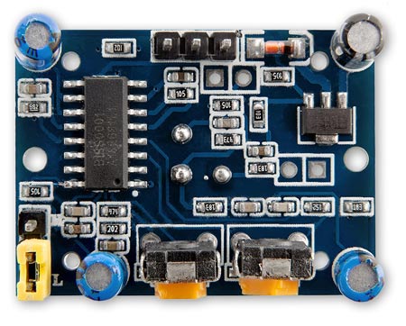
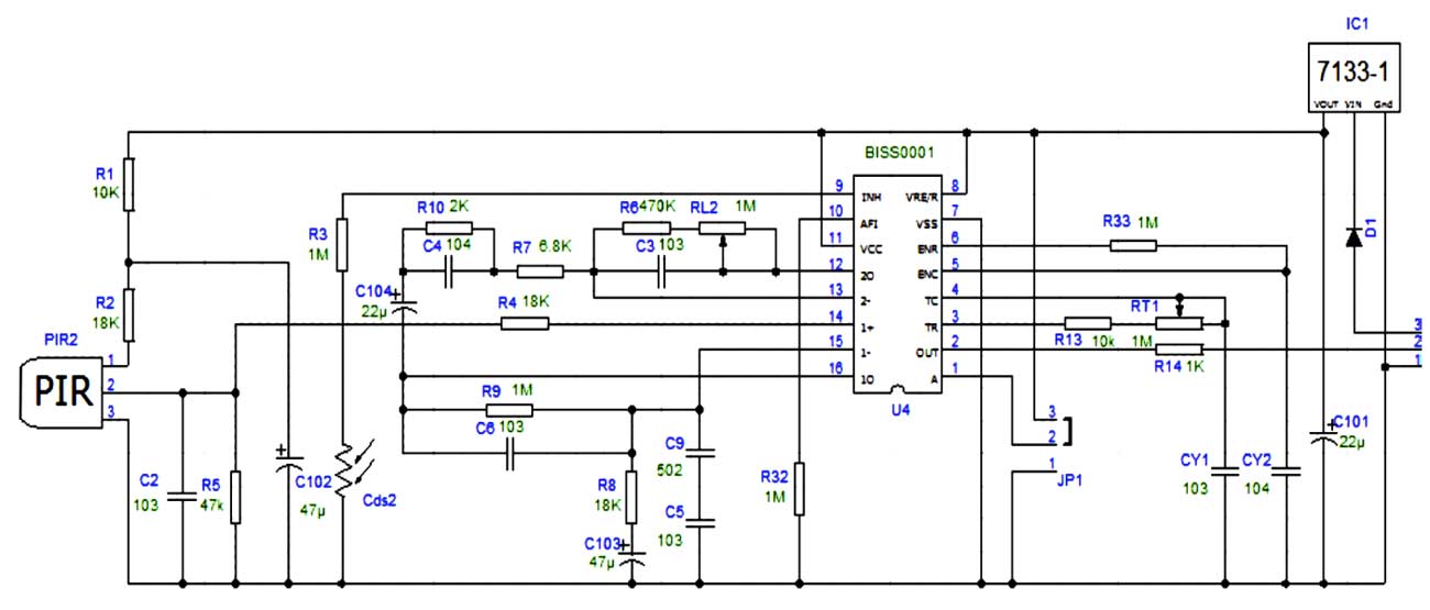
HC-SR501 PIR Motion Sensor Module
• With induction blocking time
(the default setting: 2.5s blocked time): Sensor
module after each sensor output (high into low), followed by a blockade set
period of time, during this time period sensor does
not accept any sensor signal.
This feature can be achieved sensor output time “and”
blocking time “interval
between the works can be applied to interval detection products. This function
can
inhibit a variety of
interference in the process of load switching. (This time can be
set at zero seconds – a few tens of seconds).
• Wide operating voltage
range: Default voltage DC4.5V-20V.
• Micropower consumption: Static current <50µA,
particularly suitable for battery-powered automatic control products
• Output High Signal: Easy to achieve docking with the
various types of circuit.
Adjustment
• Adjust the distance potentiometer clockwise
rotation, increased sensing distance (about 7 meters), on the contrary, the
sensing distance decreases (about 3 meters).
• Adjust the delay potentiometer clockwise rotation
sensor the delay lengthened (300S), on the contrary, shorten the induction
delay (5S).
Rear of the PIR Module showing sensor pins soldered to the PCB.
The sensor is de-soldered and wired into the sensor housing.

PIR modification to stop false triggers
When used with a wireless device the PIR module tends to false trigger when the wireless is in use.
I have added a 220nF ceramic capacitor across pins 12 &13 of the BISS001 PIR IC to help suppress noise.
The above improved the false triggering a little bit so I added a 1000μF electrolytic capacitor across the 0v and VCC pins.
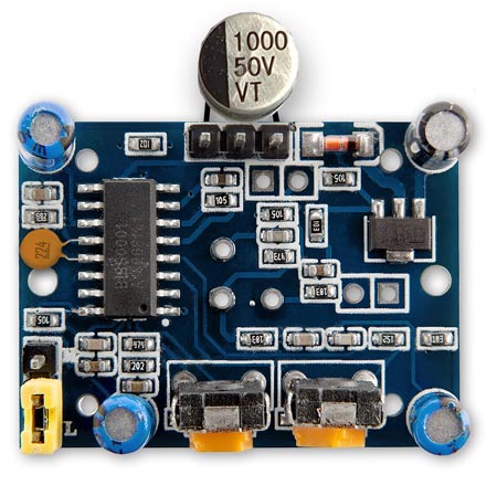
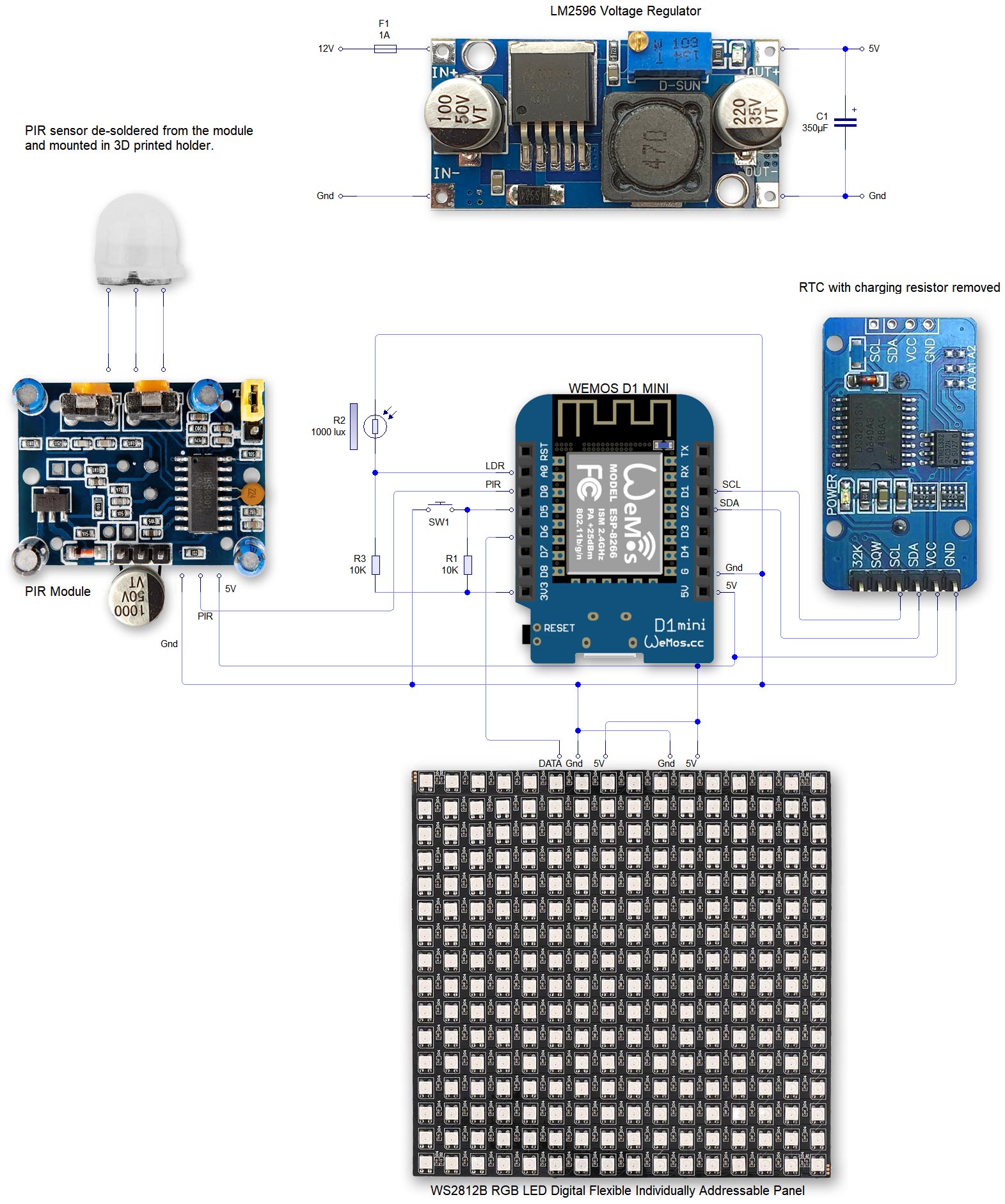
PIR Module Schematic
Alternative PIR sensor
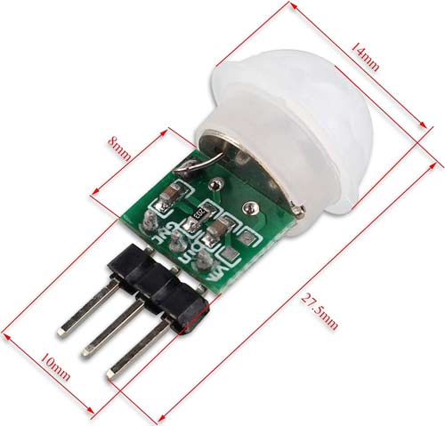
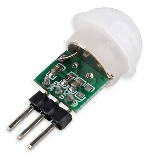
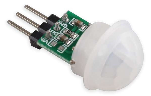
An alternative to the above PIR module is the AM312.
It does not have the adjustable range or timer of the HC-SR501 PIR Motion Sensor Module but it is not susceptible to RF noise so can be used without modification in this circuit.
Technical Parameters:
1. Working
voltage: DC 2.7-12V
2. Static power consumption: <0.1mA
3. Triggered time:
2 seconds;
4. Blocking time: 2 seconds;
5. Trigger: repeatable;
6.
Sensing range: ≤100 degree cone angle, 3-5 m; (required depending on the lens)
7. Working temperature: -20 / +60 degrees C
8. PCB Dimensions: 10mm x 8mm
9. Module Lens: Small lens
AM312 based PIR module.
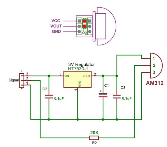
Schematic
There is a decoupling capacitor on the
regulator input and two on the 3 volt output to the PIR chip.
A 20K Ohm
resistor (R2) in series with the logic output limits the available output
current so it can only really drive a logic input or a very low gate voltage
mosfet.
There is no wrong polarity protection for the power pins. They
are marked on the pcb with a very small “+” and “-” symbol. (see the first
photo).
RTC Real Time Clock DS3231
This module stores the time from the NTP server.
The built in clock has temperature compensation and has battery backup in case of power failure.
Note the RTC module is modified (see below) to take non rechargeable batteries.
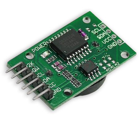
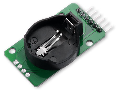
Modification of DS3231 AT24C32 I2C Precision Real Time Clock Module
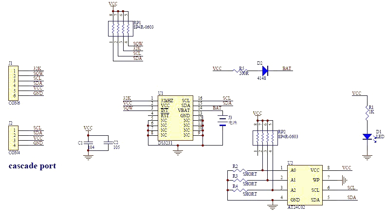
My clock uses a DS3231 AT24C32 I2C Precision Real Time Clock Module instead of a DS1307.
The module comes supplied with a Lithium-Ion rechargeable battery see diagram above. I use a non rechargeable battery so have removed resistor R5
from the module as below.
Location of R5 on the DS3231 module.
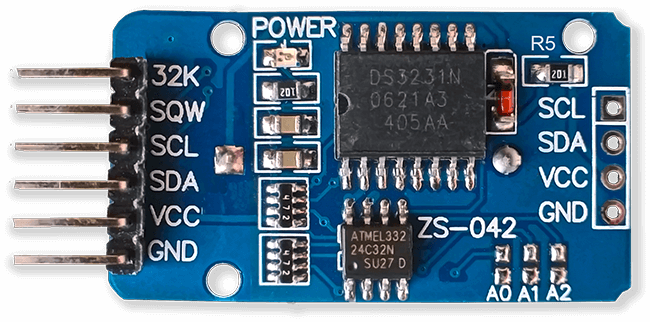
Charging Resistor R5 removed.
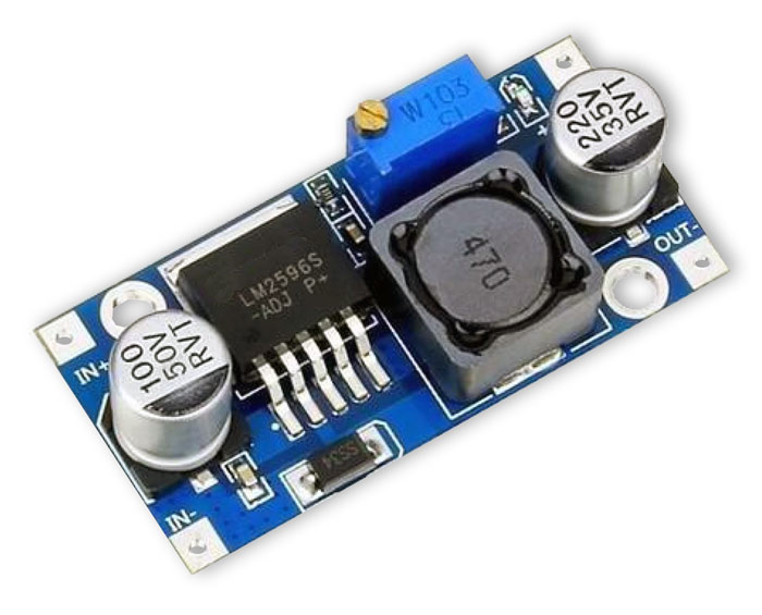
LM2596 Regulator Module
LM2596 Regulator Module drops the voltage down to 5v.
This is adjusted by the 10K preset resistor on the module and measured after the revearse protection diode D4.
Make sure the voltage is set before adding it to the board.
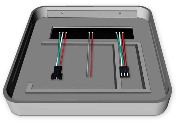
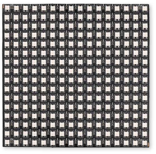
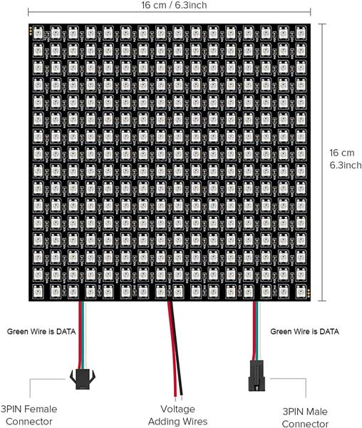
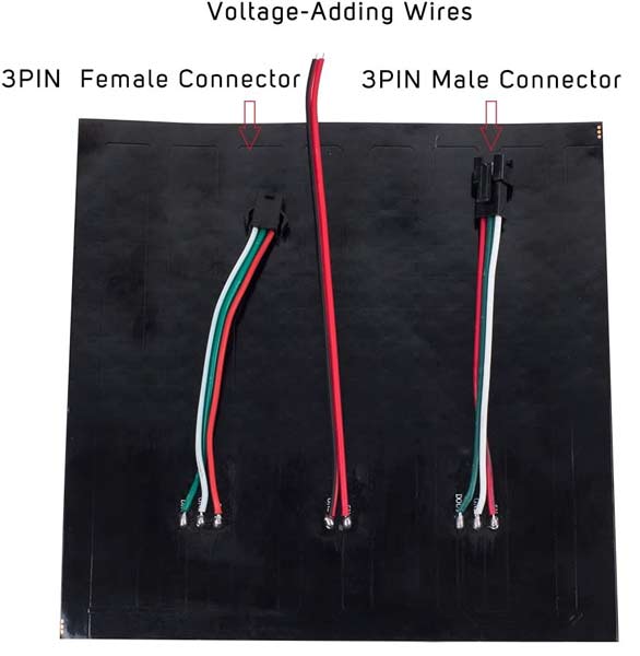
WS2812B 16x16 RGB LED Digital Flexible Individually Addressable Panel Light
Connections
Rear View
Schematic
Note 1 the modification to the PIR module to stop false triggers
Note 2 an AM312 PIR module can be used instead without modification.
Click schematic for full size version
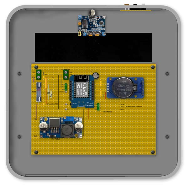
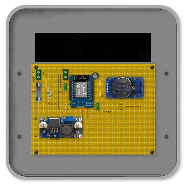
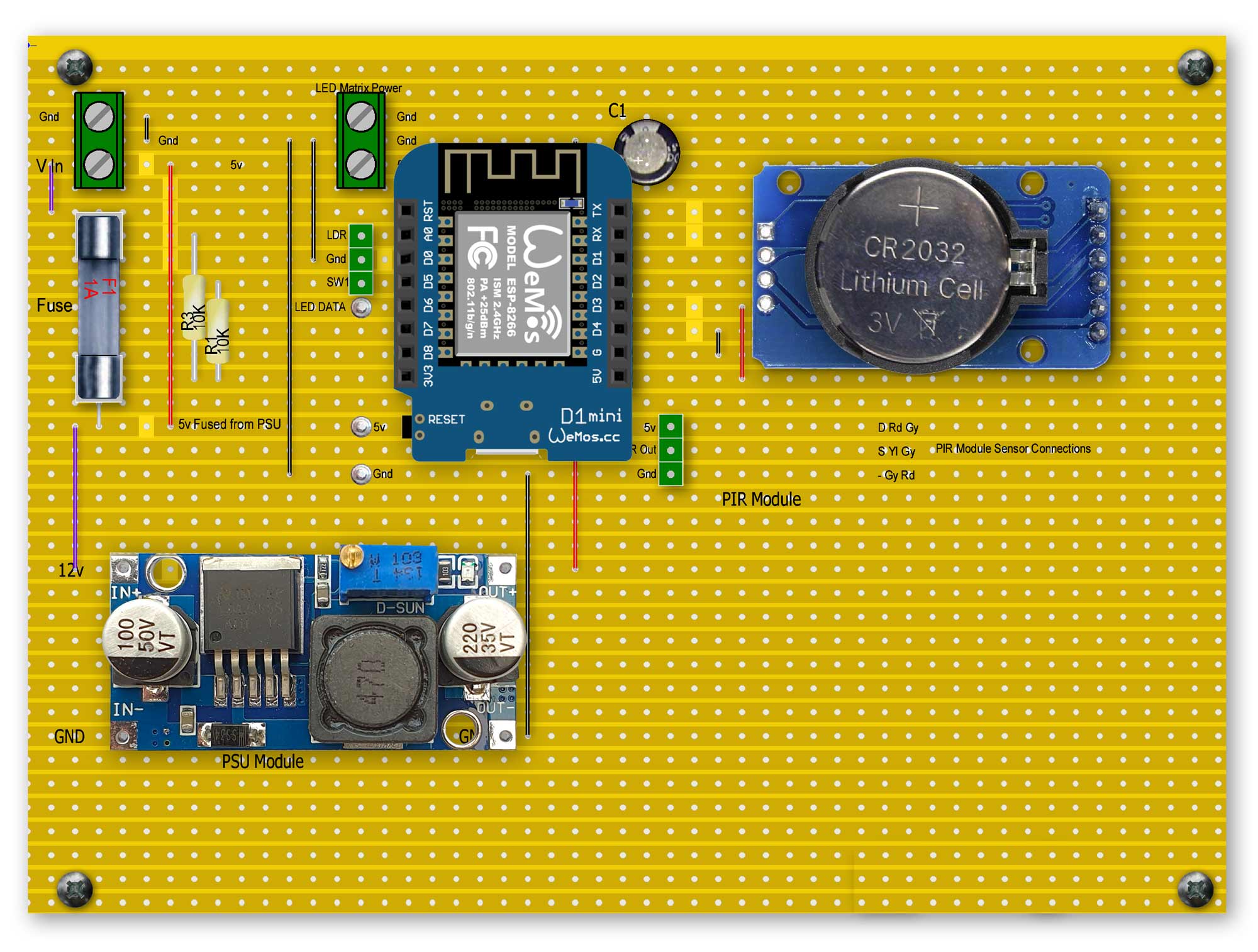
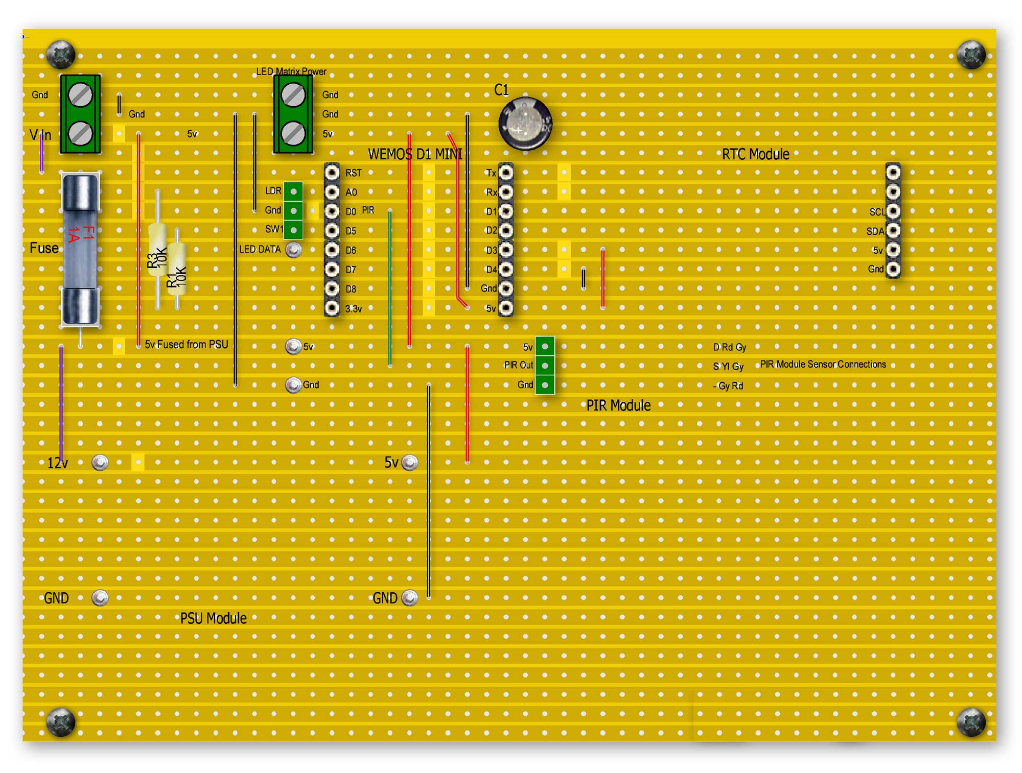
Vero Board Layouts
Main Board
Click boards for full size versions
All modules fitted
Modules removed
Rear of board
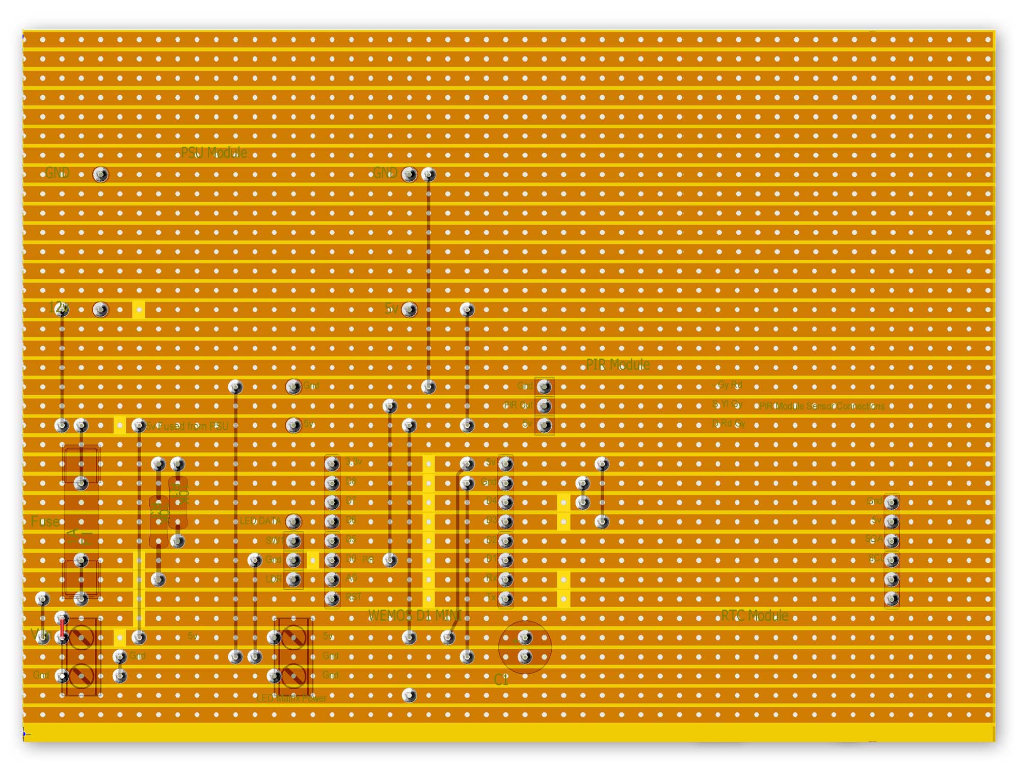
Vero Board location in rear of the clock
Switch/LDR Board
Vero Board in place with rear panel removed showing PIR PCB & Switch/LDR Vero board location.
If the AM312 PIR module is used this is housed in the PIR mounting.
The PCB is held in place on the PIR spacer by 2 x M2 self tapers.
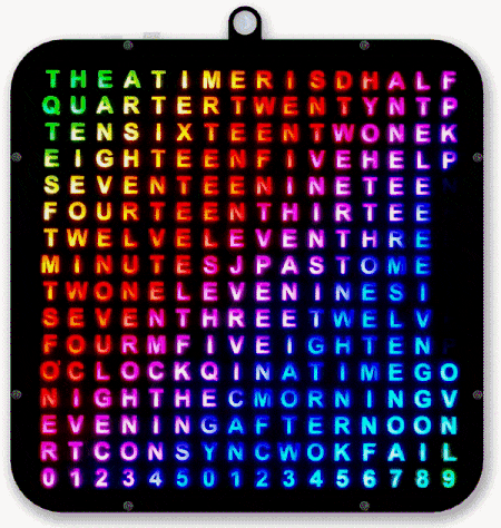
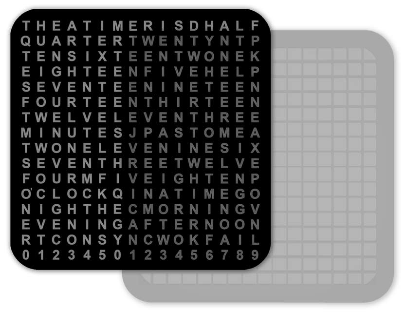
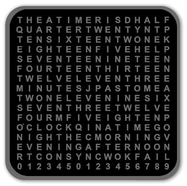
Transparent Character Display Sheet
The characters for the display are printed onto OHP inkjet film.
These sheets are very cheap and dead easy to print.
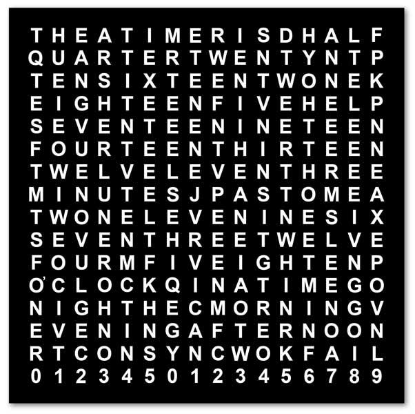
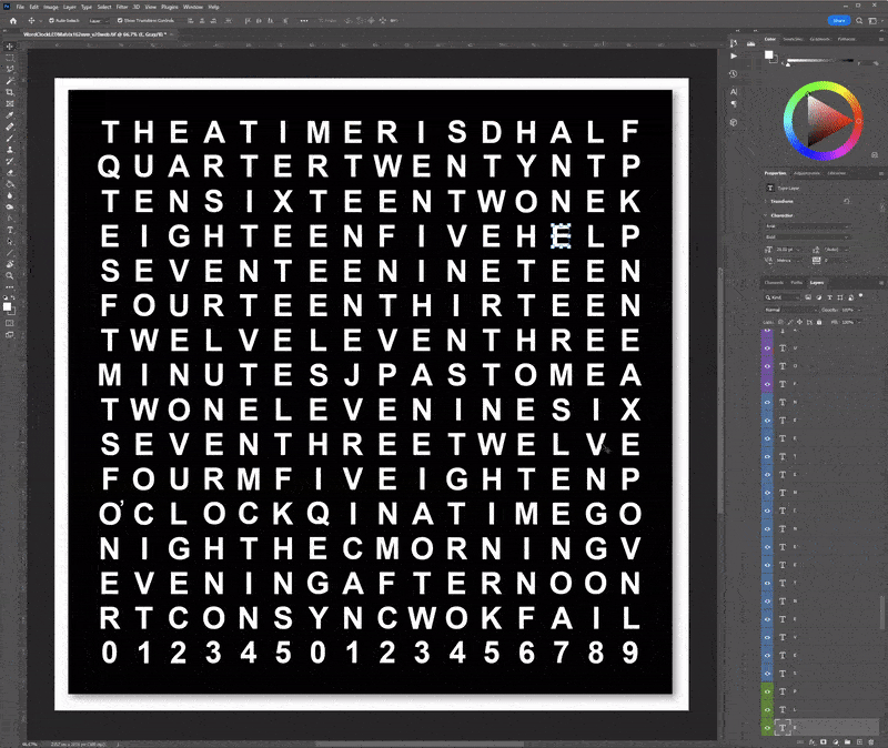
The sheet is made in Photoshop and is just a black background with white characters.
Each letter has it's own layer. To change a character just select the character with your mouse and type in a new character.
The animation below shows a character being chenged in Photoshop.
Clicking on any character selects the layer as can be seen in the layer tool bar on the right.
Each row has a different colour.
In the animation G is selected and then double clicked the letter J is typed on the keyboard and replaces the G.
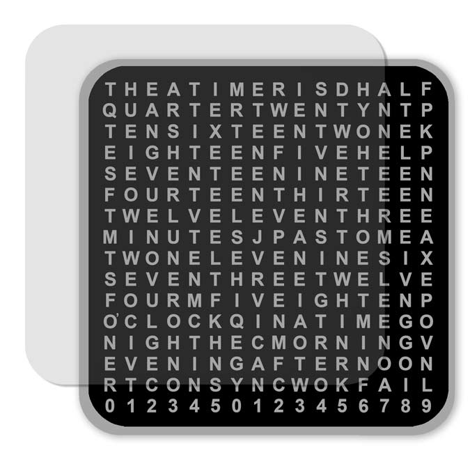
Once printed onto OHP film the characters need to be cut out from the sheet so it fits under the bezal.
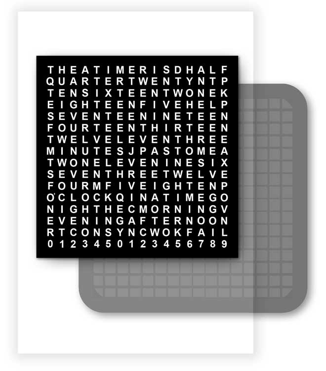
To help trim the sheet to size use the 3D printed template as a guide to cut out the sheet.
OHP sheet cutout ready to be fixed in place under the bezel and Perspex sheet.
Code