ARDUINO SERIAL TERMINAL
Serial terminal using an Arduino NANO and an ILI9341 2.8" TFT display
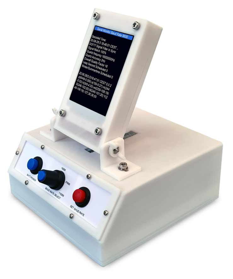
Arduino Nano serial terminal with 3D printed case.
Standalone serial monitor with USB connection or with Tx Rx connection via test clips.
Built in battery with 4 x AAA batteries.
About
I needed a portable device to monitor the serial output from my projects insitue.
This project works with the ILI9341 TFT 240x320 display and uses the hardware scrolling feature of the display.
It also uses a modified Serial Buffer to allow serial date above 9600 to be used.
Can be connected via the Nano mini USB port or via the serial in terminals.
Baud rate is set by selecting the baud rate with the rotary selector.
Once the board rate is selected pressing "SET BAUD RATE" restarts the device then starts it at the new baud rate.
The baud rate is indicated on op of the TFT display.
Arduino NANO Serial Buffer size change
The Arduino core code contains a small data buffer where you can keep throwing data at it and the Arduino code will read the data and process it in order.
However, this data buffer is by default only 64 bytes in size. This value is
hard coded in the Arduino core source code and applies to all Arduino boards,
even those with a vast amount of RAM available.
The 64 byte limit meant
that sending a burst of data longer than 64 bytes would cause data to be
truncated as the ATmega328 could not process the data sent fast enough.
The solution is easy, increase the buffer size to 1024 bytes.
The solution below was based on Hobby Electronics Arduino UNO serial buffer mod.
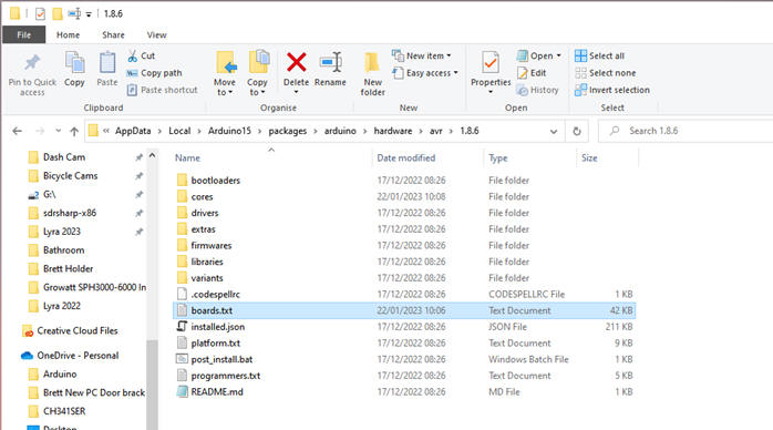
Go to C:\Users\”your name”\AppData\Local\Arduino15\packages\arduino\hardware\avr\1.8.6\cores Copy the arduino folder and paste a copy. Rename to copied folder to “arduino_1024_serialbuf”. |
|
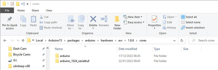 |
|
Open this folder and edit the file USBAPI.h .
|
|
Paste the new text below under the original NANO section in this file and save it. nano1024.name=Arduino Nano (1024 Serial Buffer) nano1024.upload.tool=avrdude nano1024.upload.protocol=arduino nano1024.bootloader.tool=avrdude nano1024.bootloader.unlock_bits=0x3F nano1024.bootloader.lock_bits=0x0F nano1024.build.f_cpu=16000000L nano1024.build.board=AVR_NANO nano1024.build.core=arduino_1024_serialbuf nano1024.build.variant=eightanaloginputs ## Arduino Nano w/ ATmega328P ## -------------------------- nano1024.menu.cpu.atmega328=ATmega328P nano1024.menu.cpu.atmega328.upload.maximum_size=30720 nano1024.menu.cpu.atmega328.upload.maximum_data_size=2048 nano1024.menu.cpu.atmega328.upload.speed=115200 nano1024.menu.cpu.atmega328.bootloader.low_fuses=0xFF nano1024.menu.cpu.atmega328.bootloader.high_fuses=0xDA nano1024.menu.cpu.atmega328.bootloader.extended_fuses=0xFD nano1024.menu.cpu.atmega328.bootloader.file=optiboot/optiboot_atmega328.hex nano1024.menu.cpu.atmega328.build.mcu=atmega328p ## Arduino Nano w/ ATmega328P (old bootloader) ## -------------------------- nano1024.menu.cpu.atmega328old=ATmega328P (Old Bootloader) nano1024.menu.cpu.atmega328old.upload.maximum_size=30720 nano1024.menu.cpu.atmega328old.upload.maximum_data_size=2048 nano1024.menu.cpu.atmega328old.upload.speed=57600 nano1024.menu.cpu.atmega328old.bootloader.low_fuses=0xFF nano1024.menu.cpu.atmega328old.bootloader.high_fuses=0xDA nano1024.menu.cpu.atmega328old.bootloader.extended_fuses=0xFD nano1024.menu.cpu.atmega328old.bootloader.file=atmega/ATmegaBOOT_168_atmega328.hex nano1024.menu.cpu.atmega328old.build.mcu=atmega328p ## Arduino Nano w/ ATmega168 ## ------------------------- nano1024.menu.cpu.atmega168=ATmega168 nano1024.menu.cpu.atmega168.upload.maximum_size=14336 nano1024.menu.cpu.atmega168.upload.maximum_data_size=1024 nano1024.menu.cpu.atmega168.upload.speed=19200 nano1024.menu.cpu.atmega168.bootloader.low_fuses=0xff nano1024.menu.cpu.atmega168.bootloader.high_fuses=0xdd nano1024.menu.cpu.atmega168.bootloader.extended_fuses=0xF8 nano1024.menu.cpu.atmega168.bootloader.file=atmega/ATmegaBOOT_168_diecimila.hex nano1024.menu.cpu.atmega168.build.mcu=atmega168 ############################################################## Now when you open the Arduino IDE you should bee the new NANO 1024 buffer option |
|
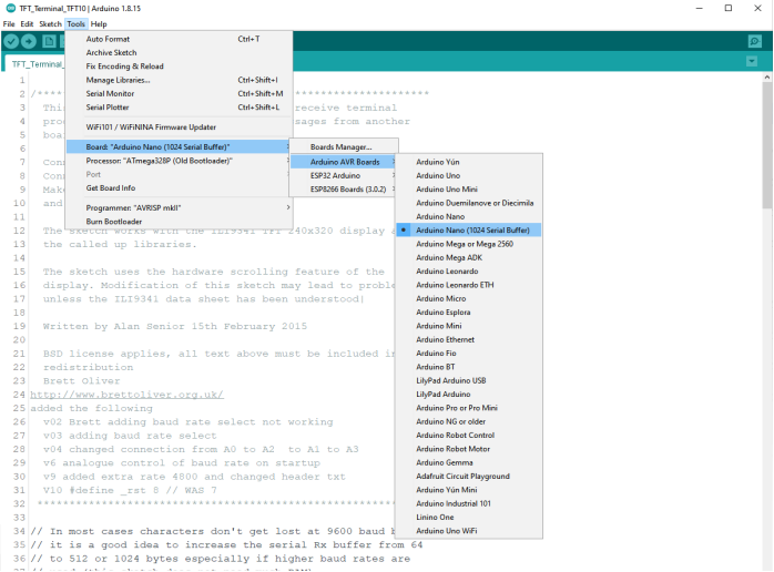 |
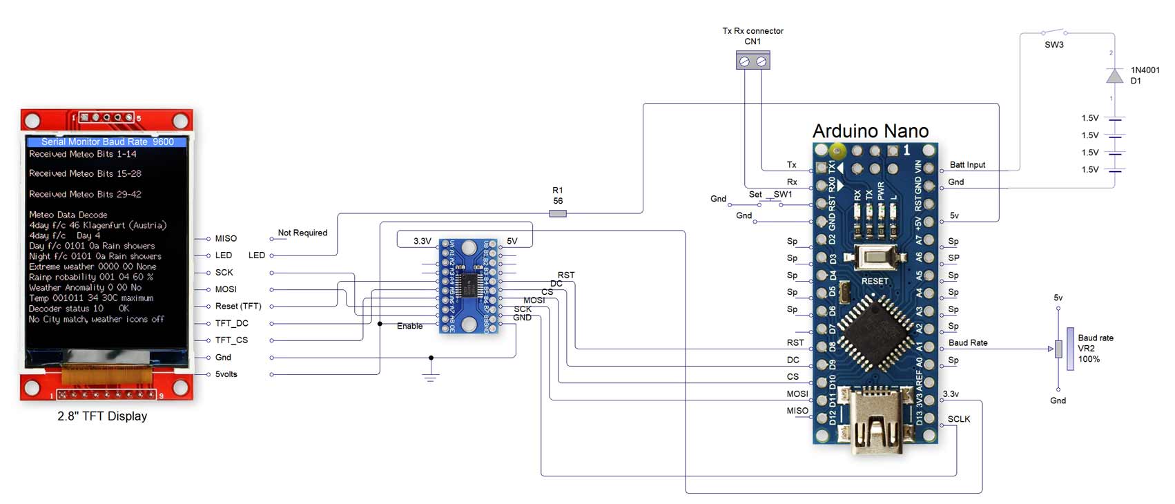
Schematic
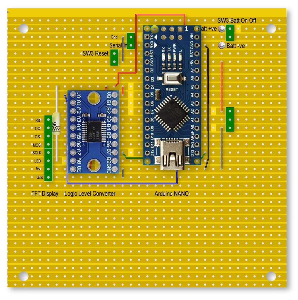
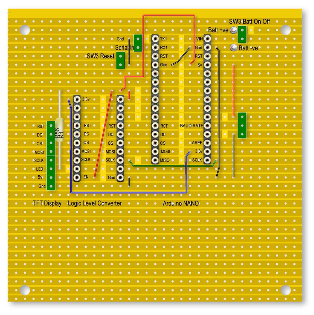
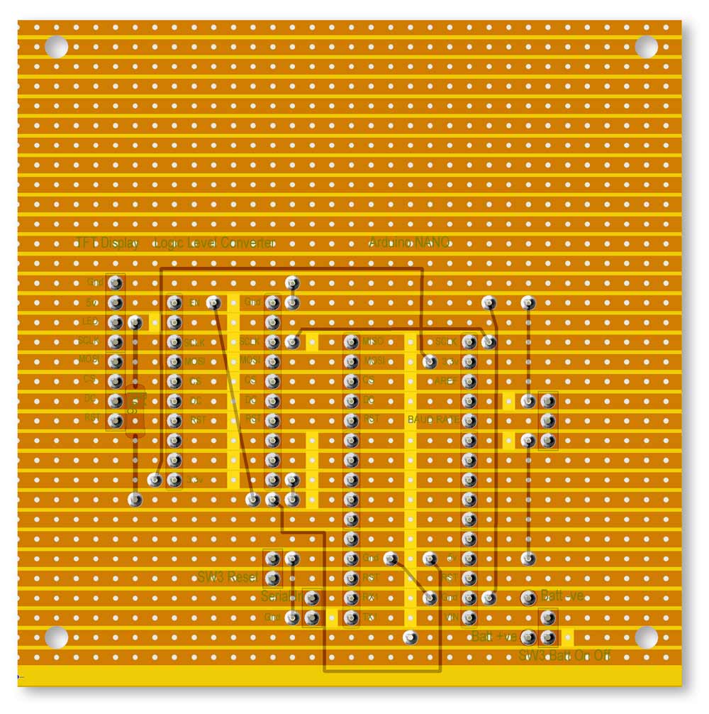
Veroboard Layouts
Layout with modules in place.
Rear layout
3D Printer Files
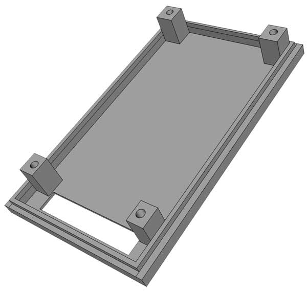
Part name: TFT_Holder
Fixes to the TFT_HolderRear with 4 M3 bolts.
Front view
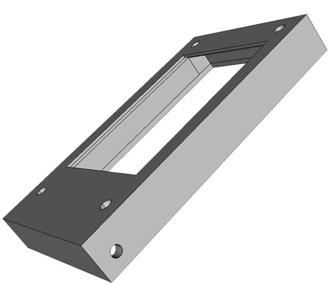
Rear View showing recess for TFT
Part name: TFT_Holderrear
Studs for 4x M3 bolts can be seen.
The M3 bolts self tap into the studs.
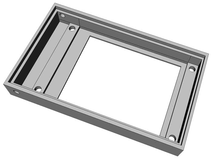
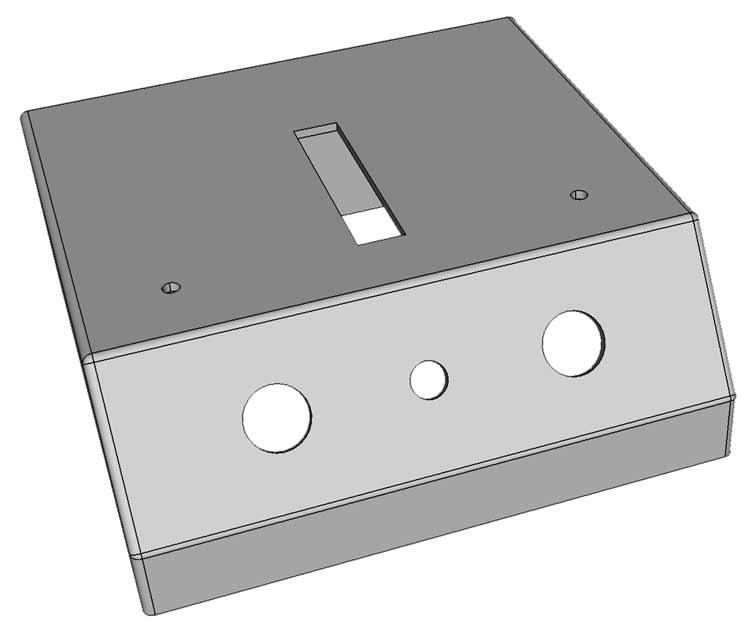
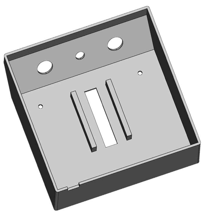
Part name: Base
Top view
Underside view
Part name: correctionspacer
2 off as required.
Glued to the dust strip holders studs protruding from the underside of the base.
Use these if narrow dust strips are used.
![]()
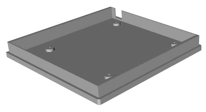
Part name: BaseCover
Push fit into the base. Veroboard mounting studs for 4 off M2 self tappers can be seen.
Part name: Bezal
This is the bezel for the Panel label.
Fixed to the base with 6 off M2 self
tappers.
Arduino Code