Section Top Remote Dimmer v2 4G Euro Module Plate Adaptor Light Strip v4 Jointing inc 3D Printed Clamps
3D PRINTED 4G EURO MODULE PLATE ADAPTOR FOR PHILIPS HUE REMOTE DIMMER V2

3D Printed plate adaptor to allow the Philips remote control to be mounted in standard 4G Euro Modules.
The Euro plate and module system is designed to offer a universal standard across the UK and EU and allows the Philips Hue remote to visually intergrate into your electrical system.
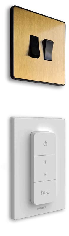
Left the standard Hue remote in it's white holder.
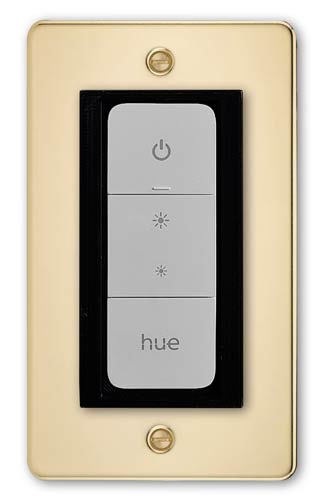
Right the Hue remote mounted in a 4G Euro plate using the adaptor.
The Hue now intergrates with style of the other electrics sockets in the house.
 |
 |
Designed around the BG Evolve range of fittings (Wickes and many online retailers) the adaptor should also work with many other manufacturers 4G Euro Modules Plates. I have tested it with Screwfix LAP plates and it fits when used with the 2mm spacer.
All you have to do is remove
the plastic insert that comes with the Euro Modules and replace it with my
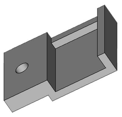
adaptor. I have included holes for standard screw on face plates in the adaptor
and spacer. The spacer can be adjusted in height as required.
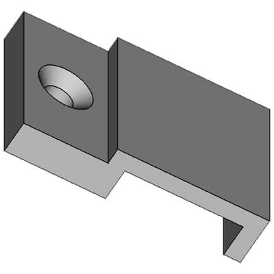
There is a square hole in the back of the adaptor to
take the original magnet that comes with the Hue remote. Just prise it out of
the inside of the Philips holder.
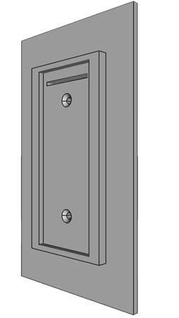
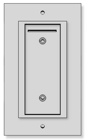
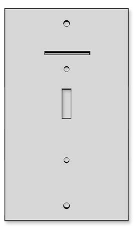
Alternative Euro plate examples
Brushed Metal
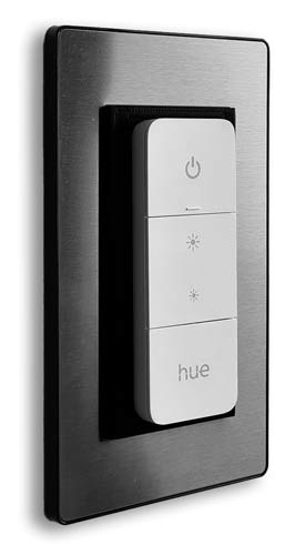
Black

The insert also has holes for screw on plates if required.
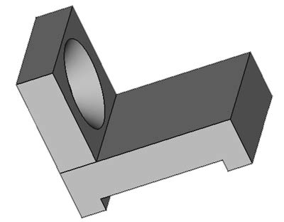
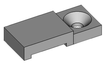
3D Printed Adaptor
Front side view
Front view
Rear view showing slot for magnet removed from original Philips mount.
A spacer is included in case more depth is required.
Adjust using FreeCAD or within CURA as required.
![]()
3D PRINTING SETTINGS
0.2mm
PLA or PLA+
Print
the adaptor on it's rear and set support touching build plate at 5% density so
the support pops off easily. Infil density was set at 20%.
Philips Hue Lightstrip Plus v4 Cutting & Joining

Philips Lightstrip Plus v4 is fine for continuous lengths but if you want to use it in a number of short lengths with gaps of no lights on between there is no easy way of doing it.
There are some 3rd party products that allow you to add in strips of cable but these work out quite expensive.
I have managed to cut the strips and join in 6w striplight cable so I can make up any run of non continous light strips.
I have designed 3D printed cable fixings to hold the light strip in place instead of using the self adhesive strip.
There are also fixings designed to clamp the joints with a built in strain releif for the 6 wire strip joint.
The cable comes in 20m lengths and is only £18.99.
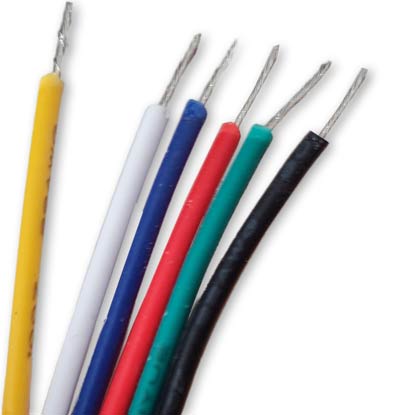
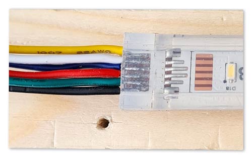
22AWG (0.65mm) 6 wire RGB+Cold White+Warm white led strip cable

Phillips Lightstrip cable v4
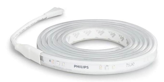
Each strip is divided into 6 sets of 3 LEDs around 330mm per section. Each section is soldered to the next and includes a section that can be cut.
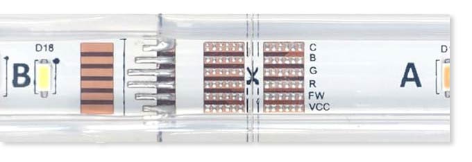
To splice a cable in between sections of strips the light strips are first cut at this point.
6 way strip cable is then soldered inbetween the 2 ends. The solder pads are quite small and can be difficult to solder but I have included a short guide on the way I carry out the operation.
Cutting & Jointing Procedure
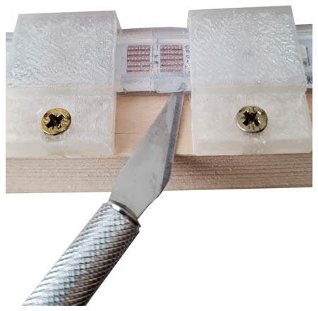
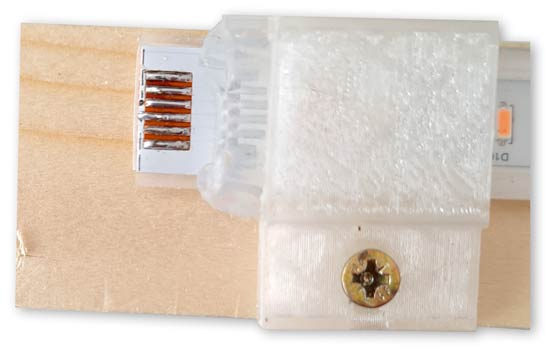
First mount the strip on a peice of softwood to hold it in place.
I have designed a 3D printed clip to hold the strip firmly in place. These are designed for mounting the strip on shelving or cabinets.

With the strip clamped in place the clear plastic strip is cut across the cut line and then level with the top of the strip sideways.
Cut the strip with scissors along the cut mark.
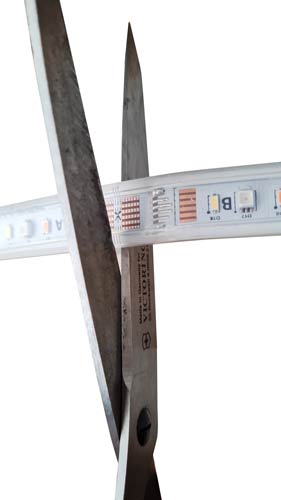
You will have now have a flap that can be folded back on each part of the cut strip.
Fold the flap back over the strip to expose the bare copper connecting strips and clamp the flap and strip in place on the softwood strip.

The bare copper strips will need to be tinned by running solder along them.
It is important not to apply too much solder and not to leave the soldering iron on the solder for too long or the solder will "dry out".
The solder should be nice and shiny and look wet.
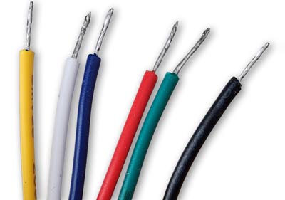
Stripping & Prepairing the 6way cable
Strip back 4mm of insulation from each wire and twist tightly.
Each wire will need to be tinned making sure there is not too much solder and the solder on each end is "wet" not "dry".
Solder each wire to a solder strip by heating the tinned strip until the solder melts then adding the wire to the hot solder.
Leave it a few seconds until the solder tinning on the wire melts.
Remove the soldering iron and hold for a few seconds until the solder sets.
Test the joint to make sure the whole length is soldered in place on the strip.
Bend the soldered wire slightly away from the next solder strip to ensure there is enough space for the next wire to be soldered.
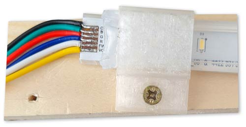
Remove the clamp and fold the flap back over the joint.
The joint is complete and is fixed in place on the joint to support the solder join.
3D Printed Parts
I have designed a set of 3D printed clamps for Pillips v4 light strips including versions with strain releif for when you are clamping over cable joints.
Parts are available in diiffernet heights depending how firm you need to hold the strips.
Heights are 4mm, 4.5mm and 5mm
Link to purchase the files for these clamps https://cults3d.com/:1955288