
Section Top Video Intro Controls Data Stramer Setup Credits 3D Printed Parts Parts List Schematic Veroboards User Manual Code/Excel Sheet
3D Printed Arduino Airgun Chronograph with 4x20 LCD display and Microsoft Excel 365 real time shot by shot analysis

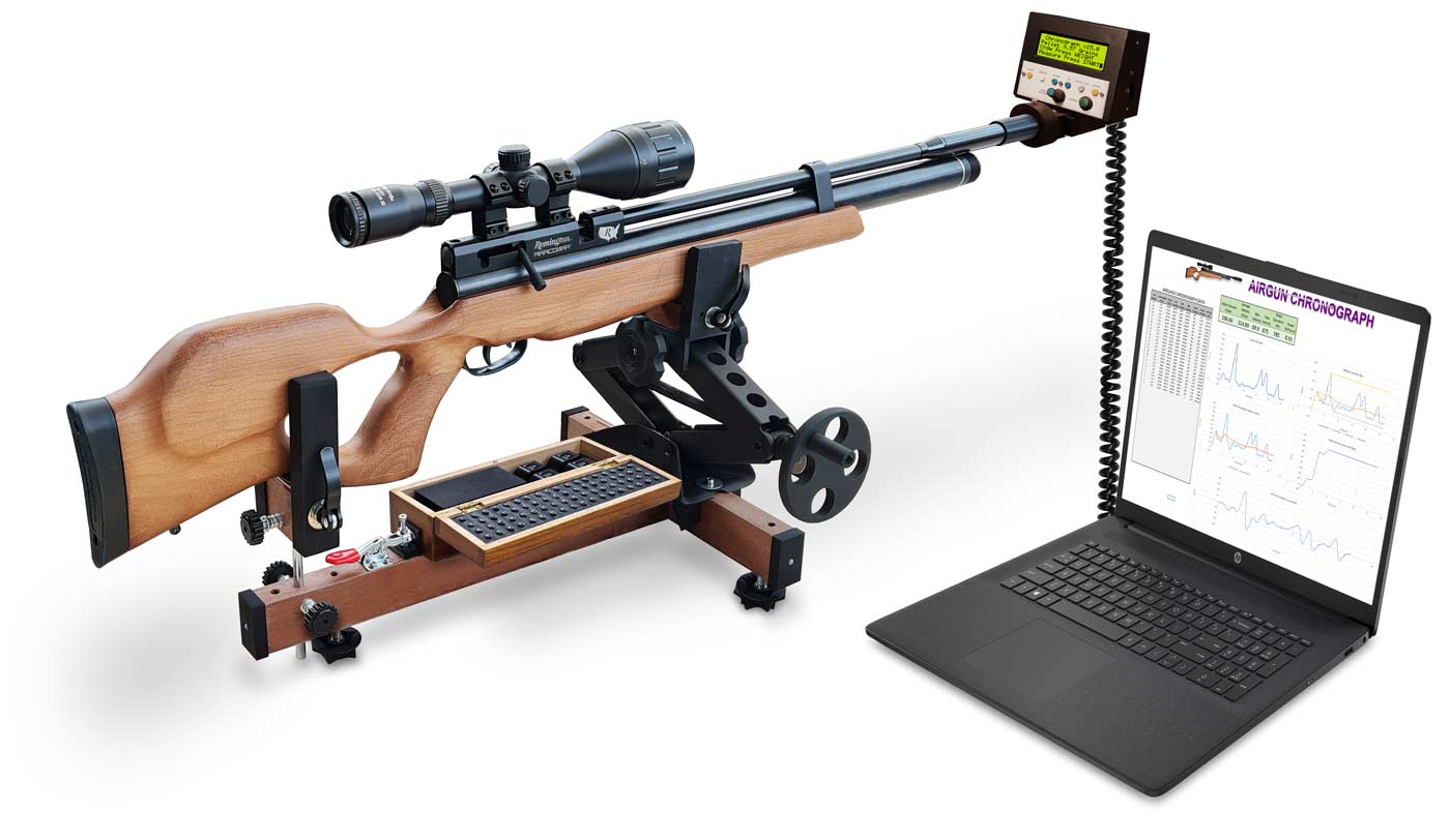
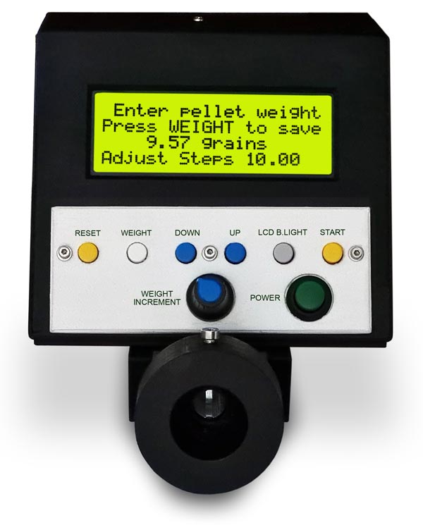
Barrel mounted 4x20 LCD display shows pellet velocity in Feet per Second including average, deviation, minimum & maximum.
The display also shows power in Foot Pound including average, deviation, minimum & maximum.
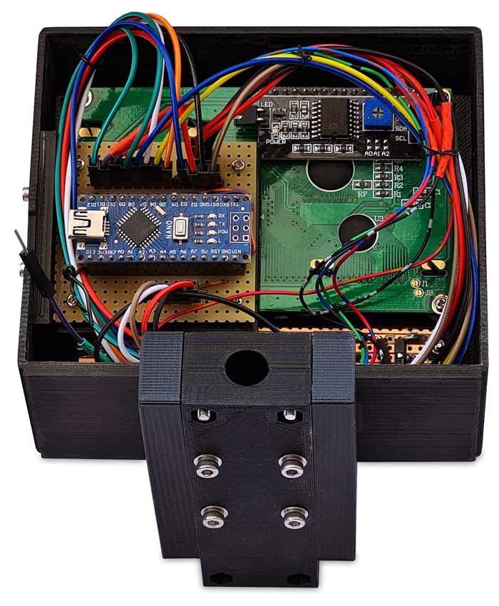
The chronograph and airgun connections are all 3D printed.
The chronograph is powered by 4 AAA batteries or USB.
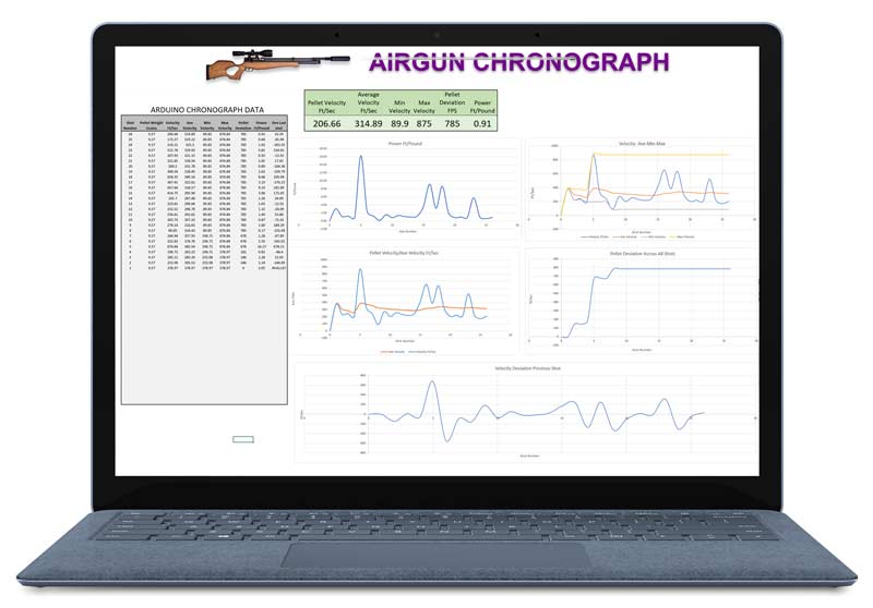
Connecting a USB cable to a PC (not available on Apple devices) with Office 365 and running the enclosed spreadsheet allows detailed live shot by shot analysis of your Airgun performance.
Video showing test shots on chronograph and Excel
Example of the included spreadsheet with 9 shot test fired showing interaction between the chronograph and the spreadsheet.

Airgun Connection
3D printed barrel adaptors have been included for standard 1/2inch UNF (Unified National Thread) barrels and also a universal slip on moderator fitting adaptor.
I have set this for my Remington Airacobra moderator but it can be changed in seconds to suit your moderator.
There is also an adaptor for fitting over larger third party moderators.
Power
The chronograph can be powered from 4 AAA (LR03) batteries or USB.
The chronograph draws 68mA with the LCD backlight off and 83mA with the LCD backlight on.
Using alkaline batteries this will give approx 10.5 hours use with the LCD backlight on and 13 hours use with the LCD backlight off.
Note I have used a Yellow/Green LCD display as the screen is visible in daylight with the LCD backlight off.
The mini USB connector from the Arduino Nano is available through a cut in the main body.

Controls
There are 8 controls on the chronograph 6 momentary push buttons, a latching button for battery power and a rotary control for pellet weight setting.
The momentary push buttons are labeled
RESET to reset the chronograph.
WEIGHT to adjust the pellet weight.
DOWN to adjust the pellet weight down and in results mode select display screen 1.
UP to adjust the pellet weight up and in results mode select display screen 2.
LCD B.LIGHT toggles the LCD backlight on or off.
START sets the chrono into measure mode waiting for a pellet to be fired.
There is a latching POWER button to turn the chronograph on or off in battery mode.
The is a rotary control to set the WEIGHT INCREMENT when setting the pellet weight.
Data Streamer
Data Streamer is a COM Add-in for Microsoft Excel that allows users to stream low latency data into Microsoft Excel from connected devices and apps.
Supported devices include
microcontrollers such as Arduino Uno, micro:bit, Circuit Playground, MXChip
Azure IoT DevKit, and any other serial capable device.
Data Streamer is a
bidirectional data transfer utility that streams data between Excel and a
microcontroller via the serial port.
This connection provides
interactivity between a data source and the powerful calculation engine of
Microsoft Excel. By using a set of commands and techniques users can design
highly interactive Excel dashboards to visualize data and control program flow.
Enable Data Streamer Add-in
Data
Streamer is pre-installed with Microsoft Excel but needs to be enabled.
To Enable Data Streamer in
Excel:
Go to File > Options
In the Excel Options dialogue click Add-ins
At the bottom of the dialogue in the Manage: dropdown
select COM Add-ins and click Go
Check the box for Microsoft Data Streamer for Excel

You should
now see the Data Streamer tab in the Excel ribbon.

Requirements
Data Streamer comes with Excel 365 Desktop.
How the Data Streamer Works
Data
Streamer connects to a data source which can be a serial device, such as the
Arduino UNO microcontroller, or a Windows 10 app via a UWP (Universal Windows
App) App Service.
The data source collects data and packages it into a CSV format and sends the data at a frequency to Data Streamer.
Data Streamer displays the data into
an Excel worksheet. Data can also be sent from Excel to the device or app.
Once connected and the Start Data button is clicked the add-in will generate 3 worksheets: Data In, Data Out, and Settings.

Data In
Streaming data is injected into a range in the Data In
worksheet. This range is updated whenever a new data packet is received.
Data Out
Data that is entered into the active range in the Data
Out worksheet is packaged in CSV format and sent to the connected device or app.
Settings
Sets the parameters for the Data In and Data Out
ranges and user settings. For more information go here.
Advanced Window
Use the Advanced Window to manage device settings,
view the serial data console, or to change global user settings. For more
information go here.
Sending Data To Your Sheet
In your code data is sent out using the Serial.print() command
Each item of data or channel must be separated by a comma. Serial.print(",");
Each line of data must be on a new line by using Serial.println();
In my Chronograph all my serial printing is completed under a function called SerialPrint()
counter_shots will be inserted
into Ch1 & pWeight into Ch2 etc.
void SerialPrint() {
Serial.print(counter_shots);
Serial.print(",");
Serial.print(pWeight);
Serial.print(",");
Serial.print(fps);
Serial.print(",");
Serial.print(average);
Serial.print(",");
Serial.print(fpsMin);
Serial.print(",");
Serial.print(fpsMax);
Serial.print(",");
Serial.print(fpsDEV);
Serial.print(",");
Serial.print(energy);
Serial.println();
}
Credits/Ideas
I searched the internet and found the following ideas I liked.
https://gadjetsblog.blogspot.com/search/label/chronograph
https://www.instructables.com/ARDUINO-AIRGUN-CHRONOGRAPH/
Both use the OPL550 and OP240 pairing to measure the elapsed time.
My Chronograph uses my favorite parts from both projects.
3D Printed Parts
All the files for my 3D printed parts are available on my Cults page.
I have printed all parts in PLA+ but PLA will be fine.

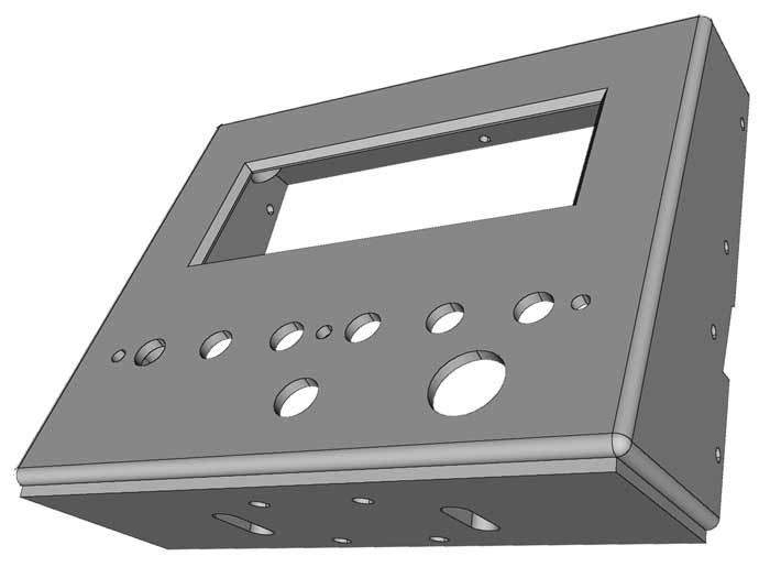
Part Name LCD_Holder
Part description Main LCD and PCB housing front
Clips together with the rear housing and secured with 5 off M2 x 5 self tapping screws
External front view
Internal view

The LCD display is fixed to the 4 raised tabs in the LCD_Holder with 4 off M2 x 5mm self tapers and 4 off M2 washers.

Part Name RearLCDHolder
Part description Main LCD and PCB housing rear
Clips together with the front housing and secured with 5 off M2 x 5 self tapping screws
External rear view with battery door cutout

Internal rear view showing the tabs that slot into the front housing.

Part Name battery_cover
Part description Cover for the battery bay
Fixed to the RearLCDHolder and is secured with 2 off M2 x 5 self tapping screws

Batteries are located in the rear panel.
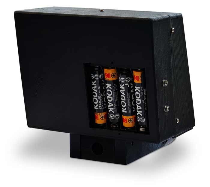
Battery cover in place held on by 2 off M2 self tappers.

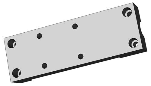
Part Name BattHolder
Part description base for fixing the 4xAAA batt holder
Fixed to the RearLCDHolder with 4x M2 x 5mm Allen bolts, 4 off M2 nuts and 4 x M2 washers
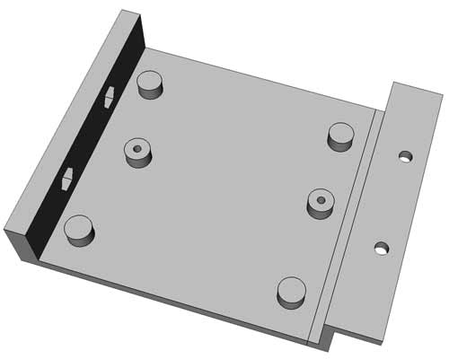
The AAA battery holder is fixed to the BattHolder with 2 off M2 x 5mm self tappers.

Part Name Button_Spacer6W
Spacer to hold the 6 tactile switches off the front panel to allow for correct protrusion of the button caps through the front panel.
Fixed to the switch Veroboard through the LCD_Holder and lablebutton with 3 off M2 x 12mm Allen bolts, 3 off M2 nuts and 3 off insulated 2mmWashers (3D printed part see below).
![]()
Fixing detail.
Button_Spacer6W shown semi transparent so you can see how it fits over the switch Veroboard below it.
![]()
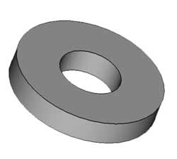
Part Name 2mmWasher
Provides an insulated mount for the metal M2 fixing nuts that hold the switch Veroboard to the Button_Spacer6W above.
Fixing detail.
The 3 black 3D printed washers fit under the M2 fixing nuts to insulate them from the copper tracks of the switch Veroboard
Part Name lablebutton
Printed/painted white this plate fits over the control knobs and buttons and provides a place for the black lettering.
Fixed through the LCD_Holder, Button_Spacer6W above and the switch Veroboard with 3 off M2 x 12mm Allen bolts, 3 off M2 nuts and 3 off insulated 2mmWashers (3D printed part see above).

Fixing detail.
lablebutton shown in position over the Button_Spacer6W and switch Veroboard allowing the controls to protrude through.
![]()
Below lablebutton panel in position on the LCD_Holder.
Along with the 3 off M2 bolts the lablebutton panel is also held in place by the potentiometer & power switch fixing nuts.
Veroboard Mounting
part name VeroHolder
Holds the main Veroboard in place with 4 off M2 x 5mm self tappers.
The holder is fixed to the side of the LCD_Holder with 2 off M2 x 5mm Allen bolts, 2 off M2 nuts and 2 off M2 washers.

Fixing detail.
4 off M2 x 5mm self tappers hold the main Veroboard to the VeroHolder.
The mini USB port of the NANO can be accessed via the cutout in the front and rear housing.
Sensor Housing
The sensors are housed in a 3D printed housing made up of 4 parts.
The connecting wires are taken up though the 2 slots in the base of the LCD_Holder and connected to the Veroboard.

The sensor housing is fixed to the base of the LCD_Holder with 4 off M3 x 25mm Allen bolts, 4 off M3 washers and 4 off M3 nuts.
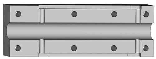
Part Name SensorHousingLeft
Top half of the sensor housing is fixed to the lower housing at the exit end with 2 off M3 x 16mm Allen bolts, 2 off M3 nuts and 2 off M3 washers.
Slots in both halves form a channel when fixed together to hold the sensors and sensor wiring.
Also held together with the 2 off M3 30mm bolts, 2 off M3 nuts and 2 off M3 washers that hold the airgun/sensor mounts to the sensor housing as well as the 4 off M3 x 25mm Allen bolts, 4 off M3 washers and 4 off M3 nuts holding the sensor housing to the LCD_Holder.
Top half of the sensor housing.
Inside view showing the large slot for the pellet to travel down as well as the smaller pairs of slots for the infra-red beam to travel between the sensor pairs.

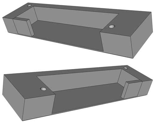
Part Name SensorHousingRight
Lower half of the sensor housing.
Slots in both halves hold the sensors and sensor wiring.

Inside view showing the large slot for the pellet to travel down as well as the smaller pairs of slots for the infra-red beam to travel between the sensor pairs.
Part Name SensorCoverLandR
These covers hide the sensor wiring and hold the 4 sensors in place.
Left and right parts are identical so one part is printed as is and is then copied & reversed in Cura before printing.
Each half is fixed the the SensorHousingRight and SensorHousingLeft with 2 off M2 x 12mm self tappers (4 off in total).
Sensor housing bolted to the base of the LCD_Housing.
Mounting the Sensor housing and the main body to the Airgun barrel
3D printed adaptors hold the sensor housing and main chronograph body to the airgun.
The chronograph is fixed to the airgun barrel in a number of different ways using adaptors with a standard socket that fits onto the sensor housing with M3 bolts.
3D printed barrel adaptors have been included for standard 1/2inch UNF (Unified National Thread) barrels and also a universal slip on moderator fitting adaptor.
Standard 1/2inch UNF (Unified National Thread) barrel adaptor.
2 parts are required to attach this to the barrel and sensor housing.
Below front part a ScrewcapThreadedGrubscrew8_83D19_3mm and rear part the connectorSensor

Part Name ScrewcapThreadedGrubscrew8_83D19_3mm
This part screws onto your Standard 1/2inch UNF barrel and fits into the round socket on the sensor mount part connectorSensor below
Barrel end

Sensor mount end

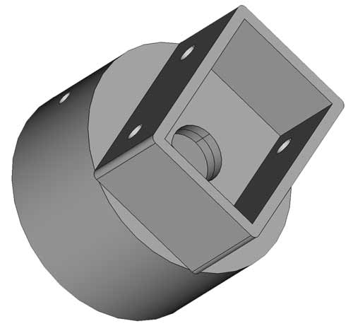
Part Name connectorSensor
The socket accepts the ScrewcapThreadedGrubscrew8_83D19_3mm part above and holds it in place with 2 Allen bolts.
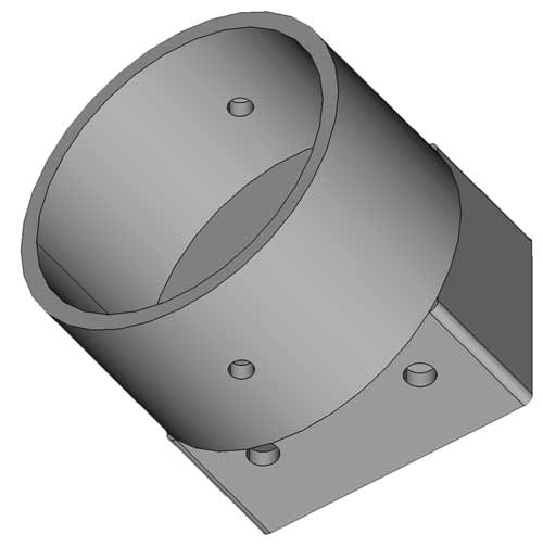
The rectangular socket fits over the sensor mount end with the 2 off M3 30mm bolts, nuts and washers.
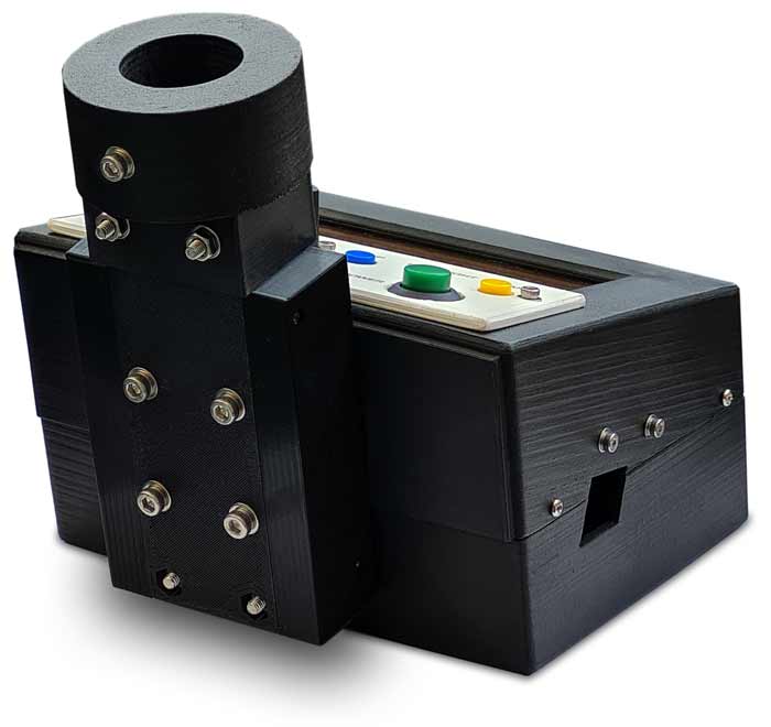
Adaptor to connect to a Remington Airacobra standard moderator
Part Name moderatorSensor
As standard my Remington Airacobra comes fitted with a moderator.
I have designed a push fit adaptor to fit over this moderator.
Will fit a M3 bolt as a grub screw if requied.
I find it's a nice friction fit without the grubscrew.

Custom fit to your rifle
I have included the FreeCAD file for this part on my CULTs page so it can be customized to suit any factory fitted moderator.
Load the file moderatorSensor04.FCStd into FreeCad.
Find the pocket ModeratorDiameter double click it and change the diameter to match your rifle.
I give it an extra 0.5mm for a friction fit.
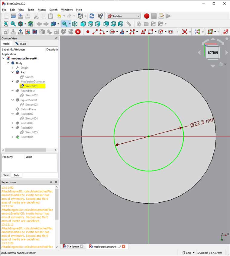
Once this is done export the stl file and print using CURA etc.
Large moderator adaptor
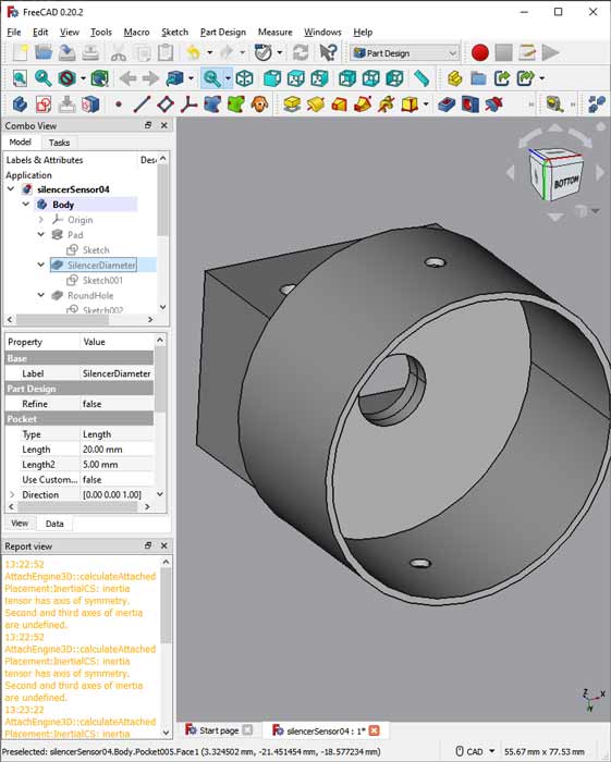
I have included a part called silencerSensor that can be customized to fit larger commercial silencers upto 40mm diameter.
As built it will fit my 3D printed silencer https://www.thingiverse.com/thing:5820619
I have included the FreeCAD file silencersensor4.FCStd

I have included the FreeCAD file silencersensor4.FCStd so you can modify it to suit your silencer.
Modify the sketch in the pocket SilencerDiameter to your own silencer.
Printing The Adaptors
I have tried to design most parts to be printed without supports.
The adaptors will all need support.
I print them with the cylinder down and 10% support touching the build plate.

This is how the adaptors look in CURA.

This is a sectional preview showing the support structure in the middle of the cylinder in turquoise.
The support pulls away easily with a pair of thin pliers.

Transfer Lettering
I have used Inkjet transfer paper for the Contol panel lettering.
Print out the image onto the transfer paper.
Carry out instructions supplied with your paper (you may need to spay with clear varnish now or after applying).
![]()
Slide the transfer in place lining up the crosses to the center of the holes.
![]()
Seal the transfer with clear varnish

Remove transfer from holes with a craft knife before giving a final coat of varnish.
![]()
Parts List
| Part | Qty |
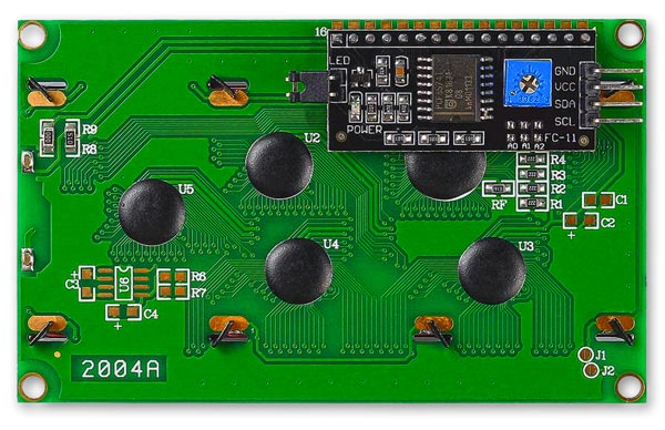
| 4x20 Green/Yellow LCD display with I2C module | 1 |
| Plastic Cap 6x6mm Tactile Push Button Switch Hat Cover | 1 pack |
| Tactile Tact Switch Momentary Tact 6x6x8mm | 1 pack |
| OP240A Sensor Infrared (IR) EMITTER IR 890NM 50MA | 2 |
| OPL550A - Optical Sensor, OPL550 Series, Photologic®, Totem Pole | 1 pack |
| Pot 10K 17mm diameter | 1 |
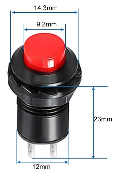
| Power Switch latching | 1 |
| Potentiometer knob 14mm diameter | 1 |
| 4x1.5V(6V) AAA Battery Holder | 1 |
| AAA (LR03) Batteries Alkaline | 4 |
| M2 x 5mm self tapper | 17 |
| M2 x 12mm self tapper | 4 |
| M2 x 12mm Bolt | 3 |
| M2 Nut | 9 |
| M2 x 5mm Bolt | 4 |
| M2 Washer | 10 |
| M3 Nut | 10 |
| M3 x 25mm Bolt | 4 |
| M3 Washer | 8 |
| M3 x 16mm Bolt | 4 |
| M3 x 30mm Bolt | 2 |
| Arduino NANO | 1 |
| Veroboard | 1 |
| Male & Female 2.54mm header plug & sockets | as required |
| Resistor R1 and R1 150R | 2 |
| Diode 1N1004 | 1 |
Notes
Nuts/Bolts/Washer/Headers - it may be cheaper to buy bulk packs of these items in various sizes.
Infrared Transmitter & Receiver
OPL550A Optek, IR
Phototransistor
All
components in this series include a photodiode, amplifier, voltage regulator,
Schmitt trigger and NPN output transistor on a single silicon chip.

OP240A Infrared Transmitter
Each dome lens OP240A and
OP245 device is an 890 nm diode that is molded in an IR-transmissive clear epoxy
side-looking package. OP240 is mechanically and
spectrally matched to the OP550 and OP560 series of phototransistors.

LCD Details
A Yellow /Green LCD is used as the letters are still visible with the backlight off.


Rear of the LCD showing the I2C adaptor
On Off switch dimensions.
The 10K Potentiometer should have a max diameter of 18mm to fit in the LCD housing.

Battery Holder
Schematic
The circuit works by using a matched pair of high speed infrared transmitters. One pair on the start of the sensor housing and another pair 60mm along the sensor housing.
As a pellet breaks the link between the 1st pair of sensors a timer is started and is stopped as the pellet breaks the link on the 2nd pair of sensors.
This time is then used to calculate the velocity of the pellet.
Click the schematic for the full size version.

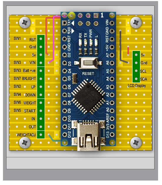
Veroboard Layouts
Main board with NANO

Main board with NANO removed
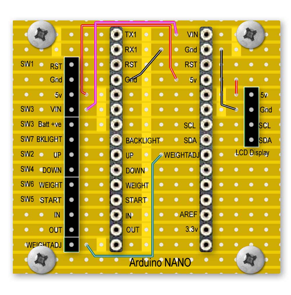
Main board rear

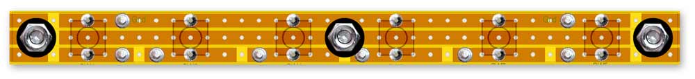
Switch Board

Switch Board rear

Board Locations
Instructions for use
Setting Pellet Weight
Press the power button or plug into a USB socket to turn on the chronograph.
When the main screen is loaded you can press the LCD B.LIGHT button to turn on the backlight.

To adjust the pellet weight press the WEIGHT button.
This will bring up the pellet weight adjustment screen
Turning the WEIGHT INCREMENT knob will change the adjustment step value on the screen.
This value will be added to or taken off the displayed pellet value depending if the DOWN or UP buttons are pressed.

For example if you wanted to change the pellet weight from 9.57 to 9.48 grains.
Turn the WEIGHT INCREMENT knob until the adjust steps changes to 0.10.
Press the DOWN button to change the weight to 9.47.
Now turn the WEIGHT INCREMENT knob until the adjust steps changes to 0.01.
Press the UP button and the pellet weight will now show 9.48 grains.
To save this new weight just press the WEIGHT button.
The chrono will restart and the new pellet weight will be changed.
The pellet weight is saved in EEPROM and will be remembered on power-up.
Note display zeroing
A quick way to zero the display is to turn the WEIGHT INCREMENT knob all the way clockwise.
The adjust steps will show the same number as the pellet weight in this case 9.57.

Press the DOWN button will will make the pellet weight and adjust steps 0.

Measuring your Airgun Performance
Once your pellet weight is set you can now measure your Airgun performance.
Checking without a PC connection

Connect the chronograph to the front of your airgun using an adaptor.
Press the power button to turn on the chronograph.
When the main screen is loaded you can press the LCD B.LIGHT button to turn on the backlight if required.

Press the START button and the display will change to "Awaiting shot"

The display will stay like this until a shot is fired or the RESET button is pressed.
When a shot is fired the display will briefly show the screen number 1 and the shot number followed by the 1st screen of the performance info.


Pressing the UP button will briefly show the screen number 2 and the shot number followed b the 2nd performance screen.


Pressing the DOWN button will return to the 1st screen.
To measure another shot press START.
Checking performance with a PC connection using Data Streamer to Excel 365
Connect the chronograph to the front of your airgun using an adaptor.
Plug a mini USB cable into the chronograph and into your PC to turn on the chronograph.
The power button can be left off to save the battery.
When the main screen is loaded you can press the LCD B.LIGHT button to turn on the backlight if required.
Chronograph mounted on a Airgun and connected to a PC collecting data.
Load the sheet AirgunChrono06.xlsm
Click on the "Data Streamer" option on the top menu.
Click on the "Connect a Device" icon far left to show connected devices.
Select your device from the list.
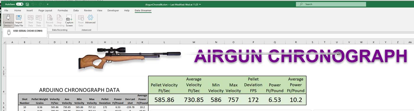
Once your device is selected the "Start Data" icon that was greyed out will now go live.
The sheet will be cleared of data ready for the first shot.

Click the "Start Data" icon.
"Start Data" will go greyed out and "Stop Data" will come live.

The sheet is now ready to accept data from the chronograph.
When the airgun is fired the data is recorded on the chronograph and the excel sheet.
Just press "START" on the chronograph to measure the next shot.
Once the series of shots are completed press "Stop Data" on the excel sheet.
The animation below shows a series of shots being recorded on the chronograph screen and in the Excel sheet.
The graphs update on each shot.
Code
Download the Arduino Nano Code

